RFIC Design

RFInsights

TX Mixer

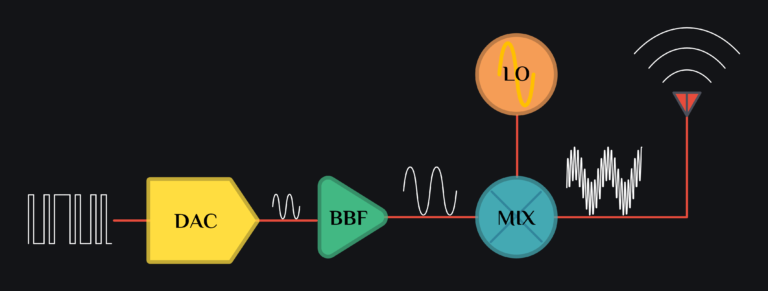
Consider a typical TX with DAC (digital to analog converter), BBF (baseband filter and/or amplifier) and MIX (mixer) as shown in image below.

TX double sideband mixer

Say DAC outputs a sinusoid signal. Let’s do some math to see what happens to the signal when it makes it to the TX output.

$$ DAC\,(t): Vcos(\omega_{bb}\,t)$$
This signal passes through some baseband circuit, say a baseband amplifier which adds 3rd & 5th order non-linearity. Signal at baseband amplifier output can be written as:
$$ BBF\,(t): \textcolor{#40ce80}{A_1\,cos(\omega_{bb}\,t)}+\textcolor{#feda39}{A_3\,cos(3\omega_{bb}\,t)}+\textcolor{#e74c3c}{A_5\,cos(5\omega_{bb}\,t)}$$
where \(A_{1}\) is a linear gain coefficient, \(A_{3}\) is 3rd order distortion coefficient and \(A_{5}\) is 5th order distortion coefficient. Read more on this in single tone distortion.

Consider an LO as a square wave toggling between +/- 1. Even if your LO signal is sinusoid, the mixer itself would/should hard switch (means switches would turn fully ON or OFF), therefore overall behavior would be as if a an ON-OFF signal (square wave) was given as LO. Developing only up to 5th harmonic of square wave, LO signals can be written as:

$$LO\,(t): \textcolor{#FFFFFF}{\frac{4}{\pi}\left[cos(\omega_{LO}\,t)-\frac{1}{3}cos(3\omega_{LO}\,t)+\frac{1}{5}cos(5\omega_{LO}\,t)\right]}$$

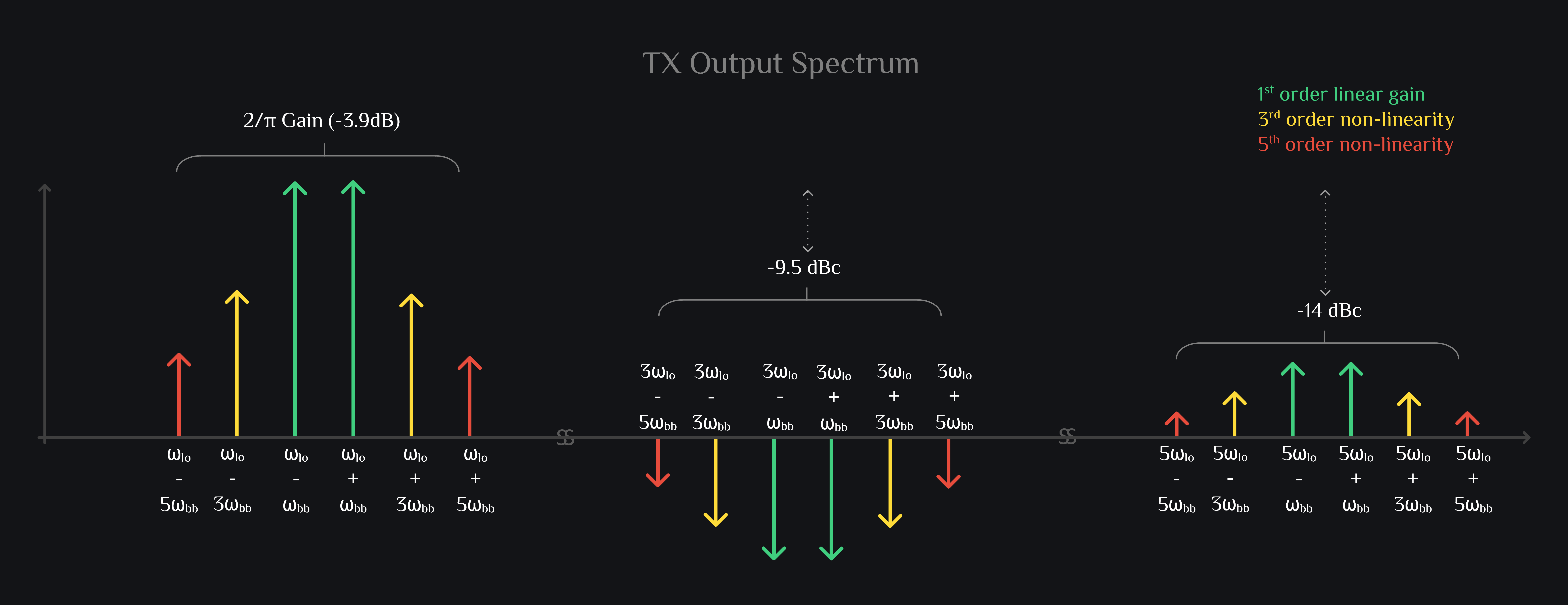
We can write mixer output as:

$$ MIX\,(t):\; BBF\,(t).LO\,(t)$$
\[ \left[ \textcolor{#40ce80}{A_1\,\textcolor{#40ce80}{cos(\omega_{bb}\,t)}}+\textcolor{#feda39}{A_3\,\textcolor{#feda39}{cos(3\omega_{bb}\,t)}}+\textcolor{#e74c3c}{A_5\,\textcolor{#e74c3c}{cos(5\omega_{bb}\,t)}} \right]. \left[ \textcolor{#FFFFFF}{\frac{4}{\pi}\textcolor{#FFFFFF}{cos(\omega_{lo}\,t)}-\frac{1}{3}\textcolor{#FFFFFF}{cos(3\omega_{lo}\,t)}+\frac{1}{5}\textcolor{#FFFFFF}{cos(5\omega_{lo}\,t)}}\right]\\ \] \begin{alignat*}{8} \\ =\frac{4}{\pi} \biggr[ & \textcolor{#40ce80}{A_1cos(\omega_{bb}\,t)}.\textcolor{#FFFFFF}{cos(\omega_{lo}\,t)}\;&-&\;\frac{\textcolor{#40ce80}{A_1}}{\textcolor{#FFFFFF}{3}}\textcolor{#40ce80}{cos(\omega_{bb}\,t)}.\textcolor{#FFFFFF}{cos(3\omega_{lo}\,t)}\;&+&\;\frac{\textcolor{#40ce80}{A_1}}{\textcolor{#FFFFFF}{5}}\textcolor{#40ce80}{cos(\omega_{bb}\,t)}.\textcolor{#FFFFFF}{cos(5\omega_{lo}\,t)}\\ +& \textcolor{#feda39}{A_3cos(3\omega_{bb}\,t)}.\textcolor{#FFFFFF}{cos(\omega_{lo}\,t)}\;&-&\;\frac{\textcolor{#feda39}{A_3}}{\textcolor{#FFFFFF}{3}}\textcolor{#feda39}{cos(3\omega_{bb}\,t)}.\textcolor{#FFFFFF}{cos(3\omega_{lo}\,t)}\;&+&\;\frac{\textcolor{#feda39}{A_3}}{\textcolor{#FFFFFF}{5}}\textcolor{#feda39}{cos(3\omega_{bb}\,t)}.\textcolor{#FFFFFF}{cos(5\omega_{lo}\,t)}\\ +& \textcolor{#e74c3c}{A_5cos(5\omega_{bb}\,t)}.\textcolor{#FFFFFF}{cos(\omega_{lo}\,t)}\;&-&\;\frac{\textcolor{#e74c3c}{A_5}}{\textcolor{#FFFFFF}{3}}\textcolor{#e74c3c}{cos(5\omega_{bb}\,t)}.\textcolor{#FFFFFF}{cos(3\omega_{lo}\,t)}\;&+&\;\frac{\textcolor{#e74c3c}{A_5}}{\textcolor{#FFFFFF}{5}}\textcolor{#e74c3c}{cos(5\omega_{bb}\,t)}.\textcolor{#FFFFFF}{cos(5\omega_{lo}\,t)} \biggr] \\ \\ =\frac{2}{\pi} \biggr[ & \textcolor{#40ce80}{A_1\{cos(\omega_{lo}-\omega_{bb})t+cos(\omega_{lo}+\omega_{bb})t\}}\;&-&\;\textcolor{#40ce80}{\frac{A_1}{3}\{cos(3\omega_{lo}-\omega_{bb})t+cos(3\omega_{lo}+\omega_{bb})t\}}\;&+&\;\textcolor{#40ce80}{\frac{A_1}{5}\{cos(5\omega_{lo}-\omega_{bb})t+cos(5\omega_{lo}+\omega_{bb})t\}}\\ +& \textcolor{#feda39}{A_3\{cos(\omega_{lo}-3\omega_{bb})t+cos(\omega_{lo}+3\omega_{bb})t\}}\;&-&\;\textcolor{#feda39}{\frac{A_3}{3}\{cos(3\omega_{lo}-3\omega_{bb})t+cos(3\omega_{lo}+3\omega_{bb})t\}}\;&+&\;\textcolor{#feda39}{\frac{A_3}{5}\{cos(5\omega_{lo}-3\omega_{bb})t+cos(5\omega_{lo}+3\omega_{bb})t\}}\\ +& \textcolor{#e74c3c}{A_5\{cos(\omega_{lo}-5\omega_{bb})t+cos(\omega_{lo}+5\omega_{bb})t\}}\;&-&\;\textcolor{#e74c3c}{\frac{A_5}{3}\{cos(3\omega_{lo}-5\omega_{bb})t+cos(3\omega_{lo}+5\omega_{bb})t\}}\;&+&\;\textcolor{#e74c3c}{\frac{A_5}{5}\{cos(5\omega_{lo}-5\omega_{bb})t+cos(5\omega_{lo}+5\omega_{bb})t\}}\biggr]\\ \end{alignat*}
Double sideband TX mixer output spectrum
Above spectrum shows that a typical mixer is double sideband in nature. It upconverted your signal to \(\omega_{lo}+\omega_{bb}\) & \(\omega_{lo}-\omega_{bb}\), and you have a copy of your signal at each odd harmonic of LO (ideal square wave does not have even harmonics so you won’t see them). All these tones are shown in green color in image above. However, these are not the only tones, you also see some yellow and red tones. These come from non-linearity of BBF. Any distortion it generates also gets upconverted. You can see here we also assumed only 3rd and 5th order terms (even terms are not there because we assume your mixer is differential, so anything even cancels out). Now out of all these tones show in image above, only one tone is desired, either \(\omega_{lo}+\omega_{bb}\) or \(\omega_{lo}-\omega_{bb}\). You want to get rid of everything else.

Let’s take a look at the time domain as well:
SSB mixer output

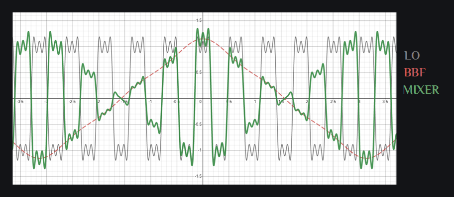
Green colored signal is what you get from your mixer output. What is this? It does not look like a nice clean upconverted sinusoid at all, so no wonder our spectrum was so polluted. Do not worry. We can work on cleaning this up. Go ahead and start from IQ mixers.

Author: RFInsights 
Date Published: 22 Dec 2022
Last Edit: 02 Feb 2023