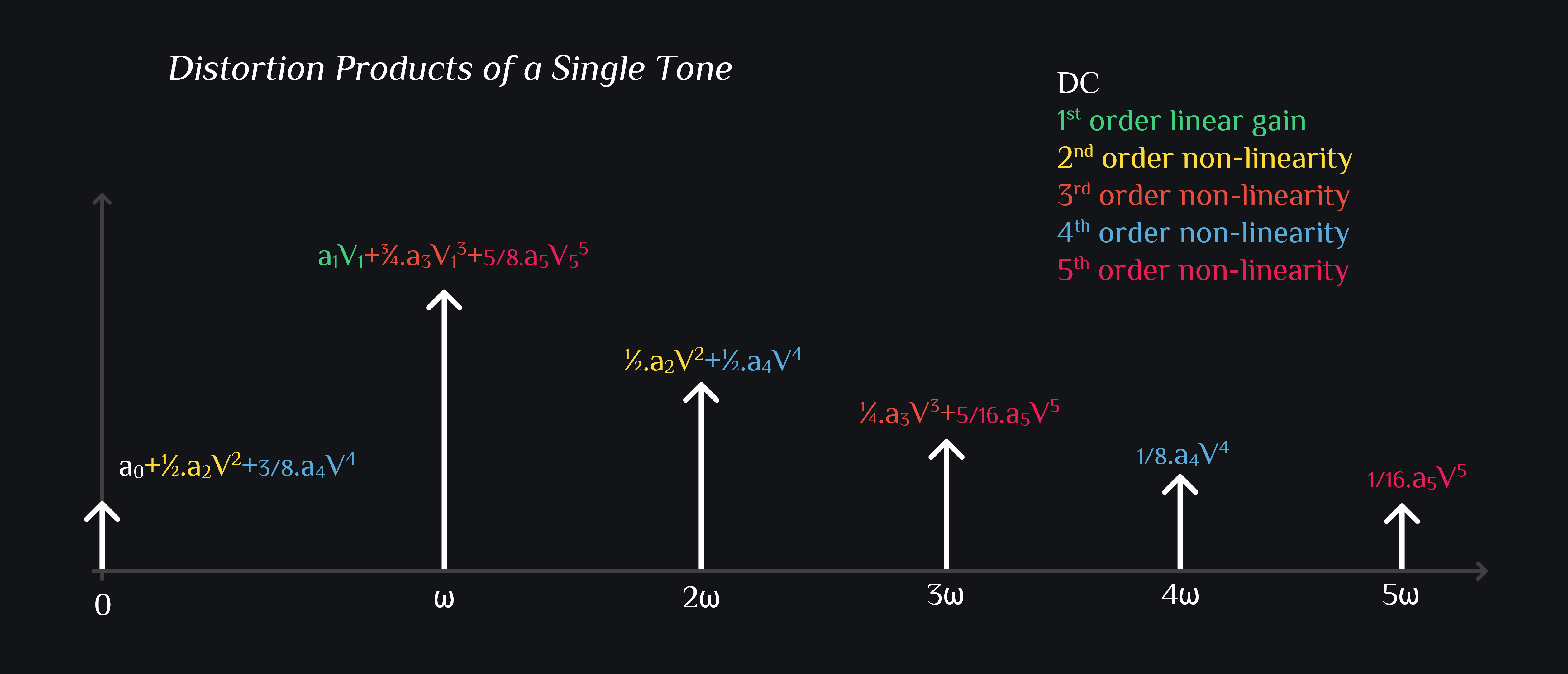
This is interesting. It shows our signal at output does not just come from linear gain, in fact 3rd and 5th (and all odd order) non-linearities contribute to your signal. Wow, great, more power to your signal! But watch out as with any sum, if a factor has opposite sign, sum goes down. And so that happens, you see our systems have typically -ive a3 (and my guess is +ive a5). These a3 and a5 are small when signal is small but as signal gets bigger and bigger, these coefficients also grow and at one point they become big enough to take your signal down by 1dB. You know it as 1dB compression point.
We can do some more math. Let’s see how a1 ,a3 and a5 are related to 1dB compression point. We can equate 1dB lower linear signal gain to overall signal gain:
The hell? What is this and what do we get from this expression? This is the voltage at which you will have 1dB compression if you knew what a1 ,a3 and a5 coefficients are for your circuit. Ok, what intuition do we get from this? Nothing.
Let’s make it more simple. Assume 5th order non-linearity is weak (not far off from reality), so lets make \(a_5=0\)
$$V=\sqrt{0.145\left|\frac{a_1}{a_3}\right|}$$
Again not much insight here. Just writing these down for notes. If you really want to interpret above expression, you can think of it this way: say your amplifier has such non-linearity that a1 and a3 are equal, then math predicts your amplifier should compress by 1dB at \(\sqrt{0.145}V\) input voltage.
This is just saying, hey don’t think 3rd harmonic only comes from 3rd order non-linearity, 5th also generates it and so will all higher order odd coefficients. So don’t let someone ask you that math says 3rd harmonic magnitude should be this much, tell them if you can model your non-linearity with just 3rd order polynomial, yes I will take your math otherwise don’t waste my time.