TX ACLR
TX is one of the most challenging (and rewarding) block in RFIC design, and ACLR is one of the key TX design spec. ACLR is a measure of out-of-band distortion (and noise) that leaks to the neighboring band. While IM3 is a great test for distortion, it leaves a lot to be desired since it is based on two-tone excitation. When a TX is excited with the desired modulated waveform that it is going to actually transmit, ACLR may come out pretty bad given what you might have predicted from IM3. That is why we need to decompose ACLR into different metrics to understand what factors contribute to it, and thereby optimize/debug it with proper insights.
Breakdown of ACLR
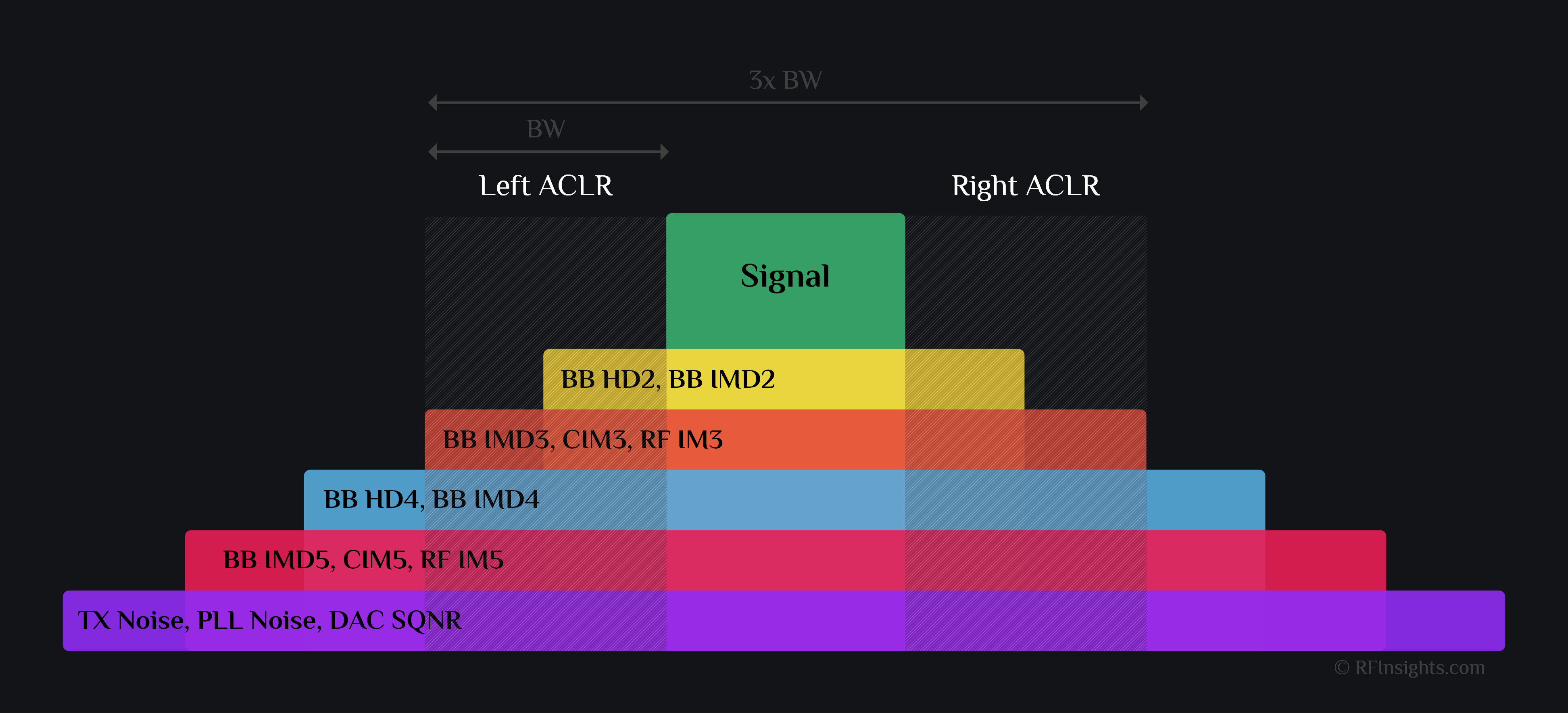
TX ACLR is composed of several distortion products as shown in image below. For acronyms, please refer to “The All Mighty IMD Table” and Counter IMs.

Observations
- ACLR regions have same BW as signal usually
- Distortion can be put in two categories:
-
- Baseband Distortion: HDs, IMDs etc. everything non-linear in baseband falls in ACLR region
- RF Distortion (means upconverted baseband signal getting distorted by mixer, PA etc.): This mostly consist of IM3 and IM5. Everything else lies far off and can be filtered out. In rare cases, say a very wideband system, IMD4 of RF distortion also makes it to ACLR region. See an example here where IMD4 lands closer to signal than IM5.
-
- The higher the distortion order, the more spread out its energy is. For example, BB HD2 power is spread over 2x BW whereas say BB HD10 would spread over 10x BW. Therefore, BB HD2 will clearly dominate ACLR than BB HD10.
- ACLR can be limited by PLL noise when your TX is very linear. More on it below.
Role of Noise in ACLR
Did you think noise is important for receivers mostly? Time to reconsider. It is very likely that your TX ACLR is limited by noise than distortion. You might have spent countless days on optimizing linearity only to find out later that DPD (digital pre-distortion) team fixed all your linearity issues and now you are failing the specs because of noise. Or you might have already designed a very linear TX and now battling with PLL phase noise violating your spectral mask. Noise can be put in two categories:- Thermal noise: This sets your ACLR floor and is dominated by TX usually. If your TX were perfectly linear, you would still have finite ACLR just because of TX thermal noise. Or if you magically fix TX noise, you would get limited by DAC quantization noise.
- Phase noise: This one is killer. Phase noise of PLL has usually dB to dB transfer function from mixer gate to TX output. Say your LO has -110dBc/Hz phase noise at 1MHz offset from LO, then your upconverted signal (\(\omega_{lo}+\omega_{bb}\)) would also have -110dBc/Hz noise at 1MHz offset. Although -110dBc may sound like a small number, when you start integrating it across bandwidth, it becomes gigantic. For example, assuming flat noise profile, -110dBc/Hz is -43dBc in 5MHz bandwidth. This limits your ACLR to -43dBc already no matter how much you optimize TX for linearity. Time to work on PLL/VCO optimization.
Author: RFInsights
Date Published: 04 Jan 2023
Last Edit: 02 Feb 2023