Estimate Noise Contribution in TX ACLR
A TX is required to comply with Spectral Mask which basically says you cannot transmit x amount of power outside of your given frequency band. As with everything in life, TX is not ideal and ends up spilling some power in adjacent bands which is measured as ACLR. This power consists of distortion and noise. Distortion power is straightforward to estimate. You run a two-tone test and see what are IM3 and different intermod levels. How do we estimate how much noise is limiting our ACLR? We integrate the noise across bandwidth. Let’s take a look at how TX noise and PLL phase noise integration is done.
Noise Upconversion in TX
Consider your LO signal has phase noise. It can be modelled as:
Now, consider a baseband signal to be an OFDM symbol. We know it is composed of multiple cosines (subcarriers), it can be written as:
Add noise to baseband signal:
which says noise is sum of cosines where \(\phi_k\) is the phase angle of the kth component, and the number of components are N = N2-N1+1. Details don’t matter, you can look it up here [1]. Just think n(t) as some noise.
Notice how LO phase noise has transferred to upconverted baseband signals. This means that every upconverted baseband tone will have LO phase noise profile across it. Also see, all of baseband noise n(t) is also upconverted around LO. This means baseband noise is additive in nature, thus only upconverts to band center (LO) where as LO phase noise is multiplicative and upconverts to all the signal tones.
Integration of Noise
TX Noise
Now that we know baseband noise is additive, we can insert baseband noise profile (flicker+thermal) at center of band (or more precisely at LO frequency) and integrate the noise which lands in ACLR region. That will be the TX noise contribution to ACLR. This is shown in image below.
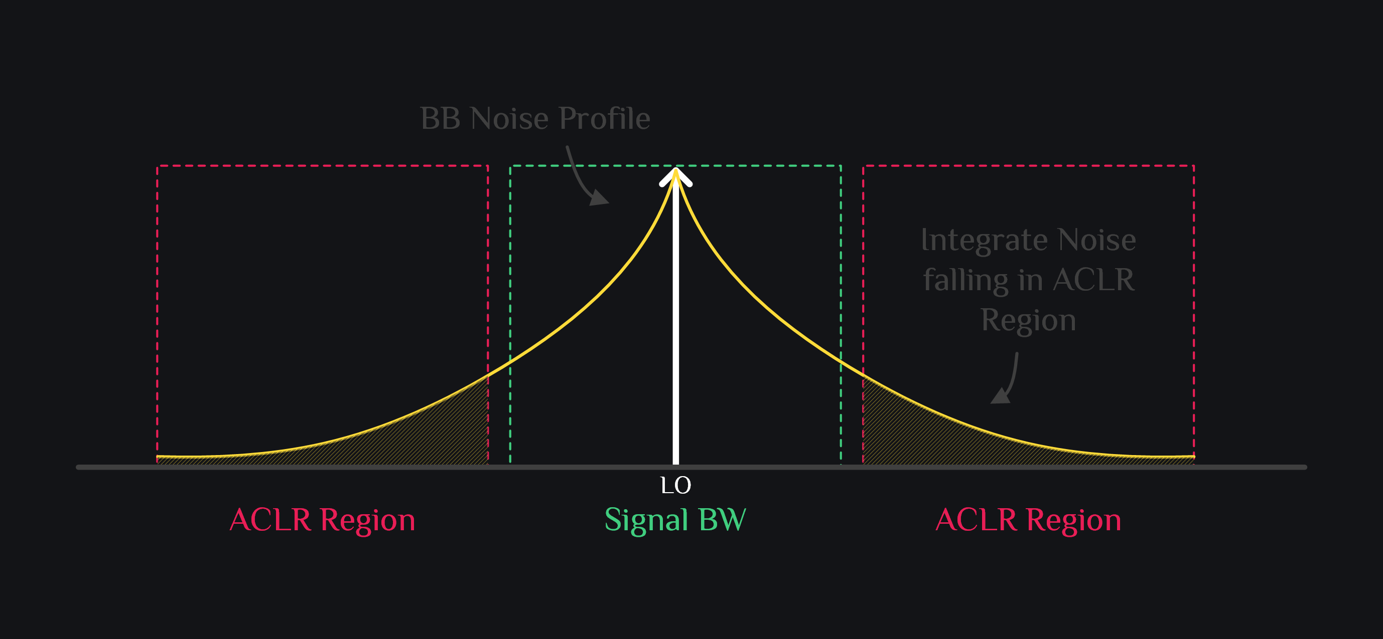
If you wanted to find in-band noise (e.g., for EVM purposes), we typically start from 1kHz as lower integration limit (i.e., we don’t go down to zero) and integrate upto BW/2. Total in-band noise is then twice of that integrated number.
PLL Noise
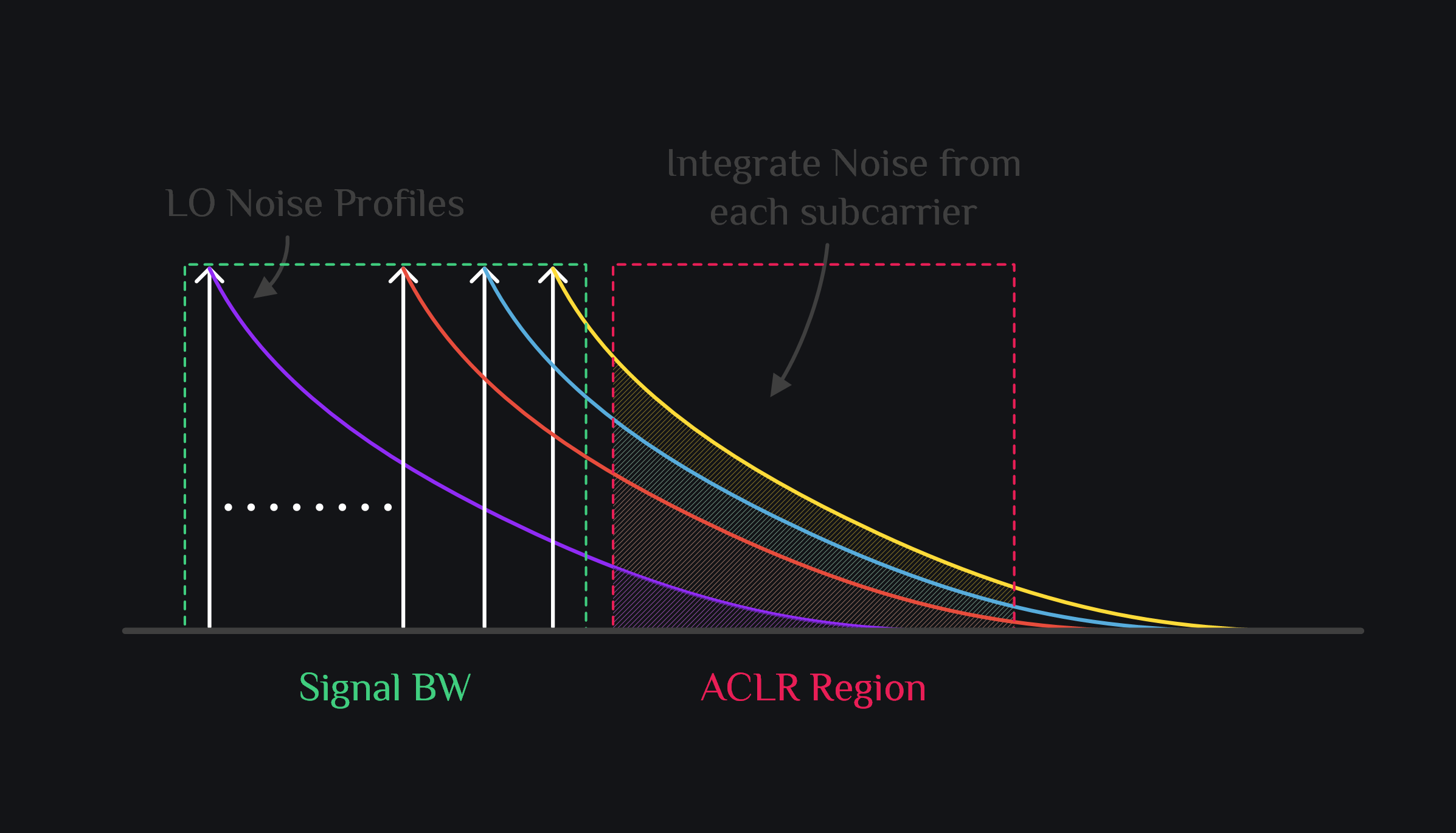
Since LO noise is multiplicative, we need to insert it across each subcarrier. Simulate and export LO phase noise data. Scale it down by number of subcarriers. Add this scaled down profile to each subcarrier, integrate the noise falling in ACLR region from each subcarrier and then sum it all up (you can try 15log() summation as this noise will be partially correlated since all subcarrier have same noise profile). This will be PLL noise contribution to TX ACLR.
Total noise in ACLR band will be the sum of TX noise and PLL noise powers.
References
[1] “Noise Power Fluctutations and Masking of Signals”. W.M. Hartmann et al. Physics Department. Michigan State University. https://web.pa.msu.edu/acoustics/pumplin1.pdf
Author: RFInsights
Date Published: 10 Jan 2023
Last Edit: 02 Feb 2023