Cadence Tips & Tricks
Stop wasting time on manual work. Use these Cadence tips & tricks to automate repetitive tasks, increase work efficiency and rather spend your saved time on doing something creative.
1. Wrap your Corners
Make a wrapper file for different corner cases to prevent yourself from inflicting the pain of different model files for different corners. In academia, most likely you are using everything typical so you wouldn’t care much. In industry, you will be asked: “Hey designer xyz, let’s simulate the noise performance at SSTTH corner”. How do you deciper it? Different industries may have different norms, but usually it means simulate with a corner that has Slow NMOS, Slow PMOS, Typical Resistor, Typical Capacitor and at hot temperature.
Ok, enough said. Make an .scs file, say cornersWrapper.scs
//**************************************

simulator lang=spectre insensitive = yes

//Syntax: MOScornerREScornerCAPcorner_NOISEflag

//Typical Corner for all

section tttt_typfnoi

include "pathToPDK/active_corner.lib.scs" section=tt

include "pathToPDK/passive_corner.lib.scs" section=rtyp

include "pathToPDK/passive_corner.lib.scs" section=ctyp

include "pathToPDK/noiseflags.scs" section=typ_fnoi

//include other model files as you need like diode, bjt etc
//corner file names might differ in your PDK, but overall idea is same that you use section keywords to define corners

endsection

//Another Example

//SS corner for MOS, slow res, fast cap corner, worse case noise models

section sstt_worstfnoi

include "pathToPDK/active_corner.lib.scs" section=ss

include "pathToPDK/passive_corner.lib.scs" section=rmax

include "pathToPDK/passive_corner.lib.scs" section=cmin

include "pathToPDK/noiseflags.scs" section=worst_fnoi

//include other model files as you need like diode, bjt etc

endsection

//Keep adding more sections for different corners
Usually PDKs are strucutred with separate model files for transistors and separate files for passive (resistor, capacitor etc). Find how yours is structured and adjust the code coresspondingly. For example, you may not have noiseflags.scs file as we had. Our process allowed us to choose different flicker noise models.
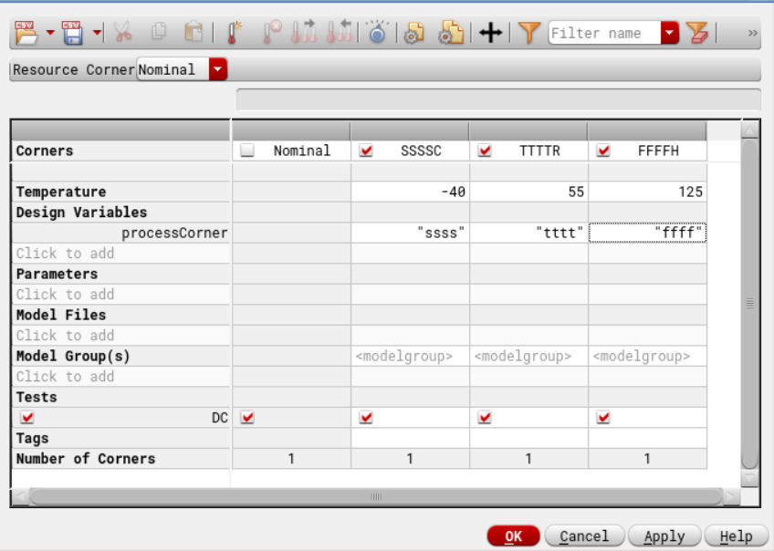
Now add this file to your model libraries in Cadence Maestro/ADEXL as shown in image below.
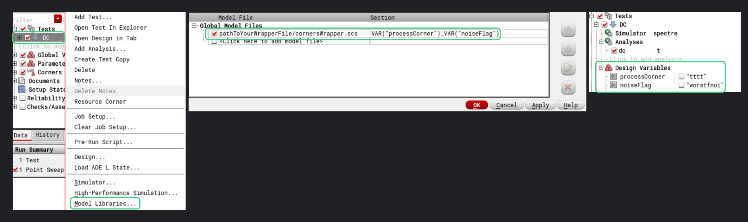
In the section column, define two variables say processCorner and noiseFlag. Netlist your test, these variables will pop up in your local variables. If the don’t, just add them yourself. Make them global or keep them local, but now you can easily control your corner with these variables. For example, we passed “tttt” and “worstfnoi” to simulate our circuit at typical corners with worst flicker noise models. Very cool and efficient!
2. Add this to your .cdsinit.local file
.cdsinit.local file is located inside the directory where you launch the cadence from.
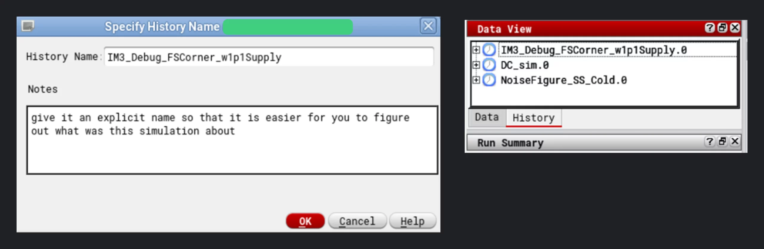
Add this and everytime you run a simulation, cadence will ask you to give your simulation a History name.
;ADEXL asks for history name
envSetVal("adexl.historyNamePrefix" "showNameHistoryForm" 'boolean t )
It helps in managing multiple simulations. You can see in history what simulations were run.
By default, Cadence plots are yucky. Set these to add your style:
;VIVA Plots
envSetVal("viva.vertMarker" "interceptStyle" 'string "On")
envSetVal("viva.horizMarker" "interceptStyle" 'string "On")
envSetVal("viva.axis" "font" 'string "Default,13,-1,5,50,0,0,0,0,0")
envSetVal("viva.trace" "lineThickness" 'string "thick")
envSetVal("viva.pointMarker" "font" 'string "Default,13,-1,5,50,0,0,0,0,0")
envSetVal("viva.vertMarker" "font" 'string "Default,13,-1,5,50,0,0,0,0,0")
envSetVal("viva.graphLabel" "font" 'string "Default,13,-1,5,50,0,0,0,0,0")
envSetVal("viva.graphFrame" "width" 'string "800")
envSetVal("viva.graphFrame" "height" 'string "700")
envSetVal("viva.trace" "symbolsOn" 'string "true")
envSetVal("viva.graphFrame" "background" 'string "#131417")
envSetVal("viva.axis" "foreground" 'string "#808080")
envSetVal("viva.axis" "majorGridForeground" 'string "#808080")
envSetVal("viva.axis" "minorGridForeground" 'string "#808080")
Cadence rounds off data before exporting it to csv, use this to increase decimal digits to 12.
;Table data export significant digit
envSetVal("viva.table" "significantDigits" 'string "12")
3. Add this to your .cshrc.local file
.cshrc.local file is located inside your home directory. Purpose of this file is to make your Linux life easy.
For example, I type goprj in terminal and it takes me to my Cadence direcotry. I type openit and it opens Virtuoso with my settings.
For example, You must have encountered cdslck in Cadence where your cellviews get locked, usually happens when cadence crashes. You can go to directory and use my killcds alias to delete all cdslck file within that directory.
setenv myhome /usr/myName
alias gohome "cd $myhome"

setnev myprj /pathToProjectDirectory
alias goprj "cd $myprj"

alias openit "virtuoso -argumentsYouWantToPass -thisMuchMemory -thisMachine &"

alias checksize "du -hs * | sort -h"

alias killcds "find . -name "*.cdslck" -exec rm -f {} \;"
4. Change Cell View using CONFIG Variables
You know you define config to choose between different cell views. Say you have two cell views for amplifier cell named as: schematic, schematic_debug. You want to simulate with schematic_debug. You would go to config, find amplifier cell and change its view to schematic_debug. You can avoid this manual work and define a CONFIG variable, there you pass the path of your cellview and it automatically switches to whatever cellview you specify. Try it, create netlist and you would see.
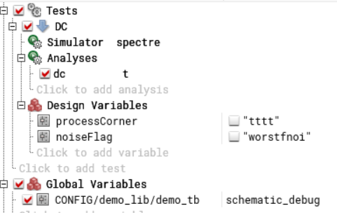
I defined a global CONFIG variable. Now it will always choose schematic_debug for /demo_lib/demo_tb cell. This is very helpful. You can quickly simulate different schematics of this cell without the need of creating different config files.
5. Maestro Tips
In-sync variables
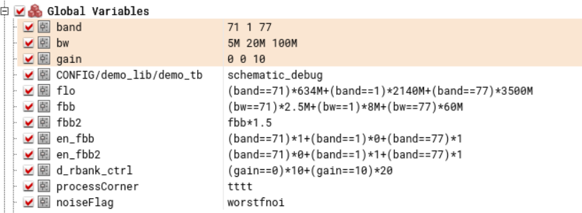
You can sweep variables in sync. Say you want to sweep a gain, you set gain variable from 0:1:5, but for each different gain state maybe you want to have different value of bandwidth, how do you do that? Right click on desired variables and set them to parametric sweep. Cadence will highlight such variables in different colors. We are sweeping band, bw and gain variable in-sync below. Cadence will simulate for (71 band, 5M bw, 0 gain) and (1 band, 20M bw, 0 gain) and (77 band, 100M bw, 0 gain)… total 3 simulations. You could have defined similar setup in corners but this has advantage over corners as it is cleaner and compact.
Define Corners
Setup process corners in corner setup instead of defining them in global variables. Use processCorner variable as we have shown above to setup transistor, resistor & capacitor corners. Define temperatures. Add necessary variables here that you would like to change over process corner (like some bias volatge etc.)
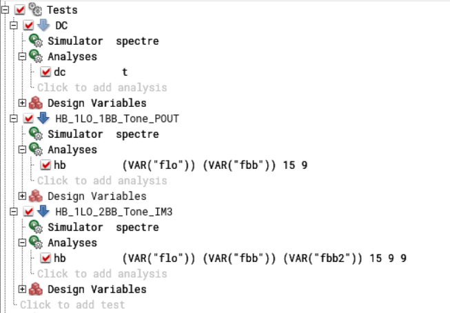
Categorize Tests
Don’t keep on adding all the analysis in one test. Add different tests for different analysis you want to do and give them explicit names. For example, have a test just for running DC sim. Make a habit of using variables. For example, you should add variables for tone frequencies in HB analysis. You see we added flo and fbb variable. Note sometimes Cadence wont accept your variable as it is, in this case surround the variable with VAR(“”) like VAR(“flo”)
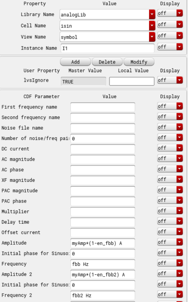
Add Enable/Disable Variables to your Input Sources
Do not keep on adding or deleting different sources you need. Make a schematic which has all the stimuli in it. Add variables to your source to enable or disable them. For example, we have a current source below. We can enable two tones, one tone or no tone by setting en_fbb and en_fbb2 variables.
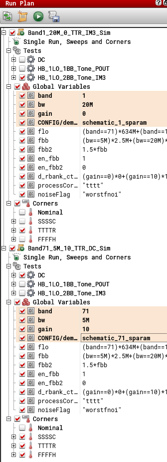
Use Run Plan
This is an awesome feature hiding in plain sight. Go to create > create run plan. Say you want to run different simulations with different conditions. Maybe you want to run IM3 sim for Band1 with 20M BW at TTR coner. Maybe next you want to run DC sim only for Band71 with 5M BW and gain of 10. You can create a run plan for these as we show in image below. Choose corners, tests and variables as you would like. You can schedule run this next when this one finishes. Go ahead explore more! This is great because you don’t need to babysit your data collection anymore. Make a run plan on Friday and run it over weekend.
6. Variable Manager
This is more of a work efficiency enhancement hack than a Cadence tip but believe me if you adopt it, life will be much easy. It is going to take some time to set it up, but IT WILL BE WORTH IT. Enough hoopla, tell me what is it. Sure.
The idea is export your global variables and manage them in Microsoft Excel. This is helpful because:
- It is easy to manage tens of variables in Excel than Cadence
- When multiple designers are sharing same workspace, each will make his/her own copy of maestro, change some variable settings here and there inadvertently or intentionally. Having an Excel file would be a way to sanity check if everyone’s global variables match.
- It would provide a clean way of sharing what are the latest and greatest variable values for each individual block. Designer of each block would update the Excel file and ask “Guys, I updated droop setting of BBF in Excel, please pick them up ASAP to reflect the latest changes in your maestro. I am also checking in my maestro for reference.”
Variable manager would look something like the image below. Download a copy here.
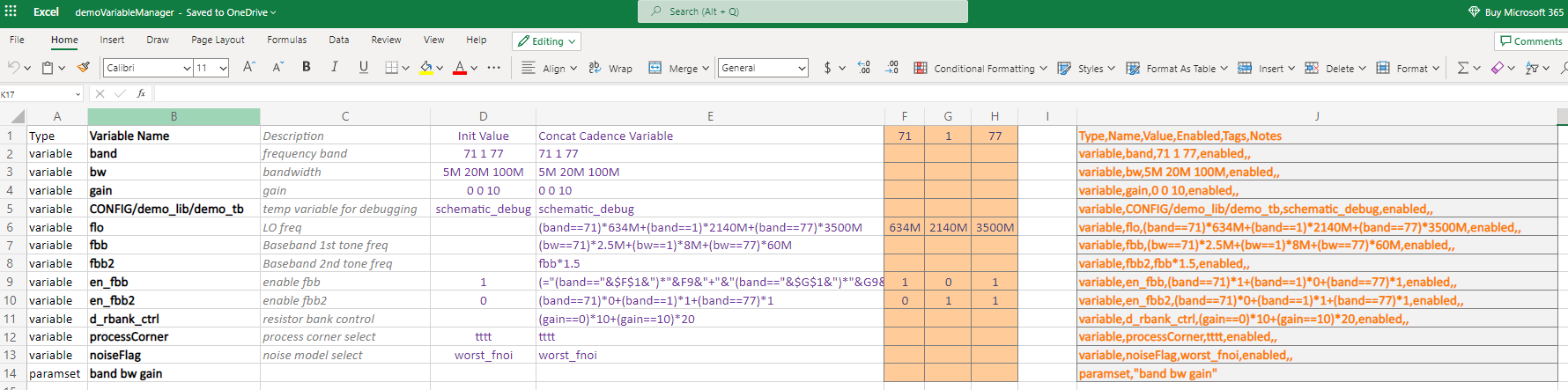
Col B: Variable name. The name of your global variables.
Col C: Description. Give your variables a purpose to make it easier for you and other users to remember what is what.
Col D: Init Value: The default value of the variable.
Col F,G,H: These columns are specific to your needs. For example, we wanted to have different values of some variables depending on what band user chooses. So we add all the bands (71,1,77) as columns, give them proper values (like you can see we are changing flo)
Col E: This is the value that will go into Cadence. Here you want to pick up the value from Init (Col D) or a concatenated value from Col F,G,H. For example, you see our flo value is concatenated version of band 71, 1, 77. If user selects 71, flo would be 634M.
Col J: This is the csv file with formatting that Cadence like and let you import into it. Download demo var manager to see how we concatenated different columns to make Col J.
Copy Col J, paste it in text file and save as csv. Note if you export csv from Excel itself, you will likely run into some formatting issue. We recommend copy to text file and save as csv. Once you have csv file, go to maestro, right click on Global variables and import.
Variable Comparison is shown in image below. Purpose here is to check if your Cadence global variables match to what you have in Variable Manager.
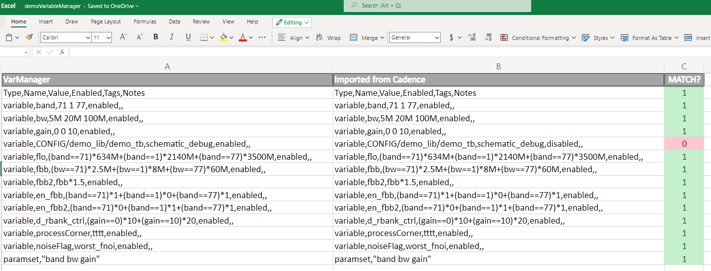
Col A: Variables from Variable Manager (Col J of Variable Manager above)
Col B: Export variables from Cadence in csv file. Open csv file, and paste it here.
Col C: Checks if variables match. If not, see what is the latest value from variable manager and ask around if it is expected.
RFInsights
Date Published: 18 Dec 2022
Last Edit: 08 July 2023