Decimal to Binary Decoder in Cadence using Verilog
Write verilog code in cadence to design decimal to binary decoder. Get rid of excess voltage sources you have been throwing around in schematic, be smart and work efficient.
1. Design Symbol
Let’s make a 6-bit decimal to binary decoder. Create a symbol as shown below:
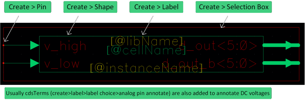
- v_high and v_low are inputs which define what high and low logic voltage level we want.
- d_out<5:0> is 6-bit binary output, and d_out_b<5:0> is active low version of it.
Now create a verilog file by going to create > cellview > from cellview
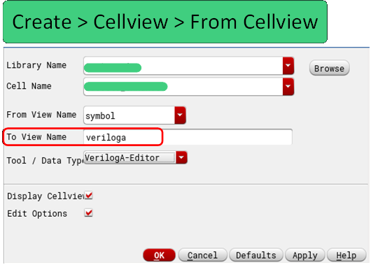
It will generate a verilog cellview with following code:
//VerilogA Module for 6bit Decimal to Binary Decoder

`include "constants.vams"
`include "disciplines.vams"

module busset6_enhanced(d_out,d_out_b,v_high,v_low)

output [5:0] d_out;
electrical [5:0] d_out;
output [5:0] d_out_b;
electrical [5:0] d_out_b;
input v_high;
electrical v_high;
input v_low;
electrical v_low;

endmodule
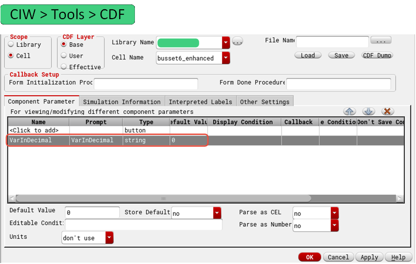
Next, we need to edit CDF properties of the cell to add input form for decimal variable. Let’s call this variable “VarInDecimal”, add it as shown in below (note CIW is Cadence window, the very first one that pops up when we launch Cadence):
2. Verilog Code
Edit verilog file and add decimal to binary conversion code. This is the complete verilog file:
//VerilogA Module for 6bit Decimal to Binary Decoder

`include "constants.vams"
`include "disciplines.vams"

module busset6_enhanced(d_out,d_out_b,v_high,v_low)

output [5:0] d_out;
electrical [5:0] d_out;
output [5:0] d_out_b;
electrical [5:0] d_out_b;
input v_high;
electrical v_high;
input v_low;
electrical v_low;

parameter integer VarInDecimal = 0  from [0:63];
analog begin
	generate i (5,0) begin
		V(d_out[i]) <+ (VarInDecimal&(1<<i))? V(v_high): V(v_low);
		V(d_out_b[i]) <+ (VarInDecimal&(1<<i))? V(v_low): V(v_high);

endmodule
3. Code Explanation:
- parameter integer VarInDecimal defines a integer variable to which user can pass valu
- 0 from [0:63] means default value 0, and range from 0 to 63 inclusive, if user passes variable value outside of this range, it will throw an error
- <+ is contributor operator, it is used to give value to continuous signals, cannot use =
- generate statement is a looping construct that can contain analog operations. Syntax generate x (startValue, endValue, step) begin
- 1<<5 → 1 left shifted by 5 → 100000
- Say binary of VarInDecimal is 001010, Bitwise & of VarInDecimal and 1<<5 would be zero, meaning 6th bit is zero so it will output v_low.
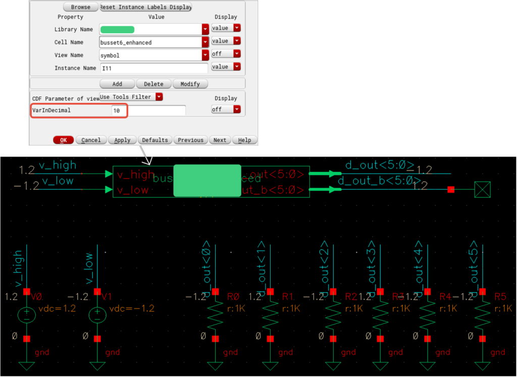
4. Testing Binary to Decimal Decoder
Time to hook this symbol up and test it. I use 1.2V as v_high and -1.2V as v_low and set VarInDecimal to 10. We can see it did give out [-1.2,-1.2,1.2,-1.2,1.2,-1.2] which is 10 in binary.
Author: RFInsights
Date Published: 24 Sep 2022
Last Edit: 01 Feb 2023