A Journey from Resonance to Impedance Matching
Chp. 3: Passive Amplification using Quality Factor
The Story of Unsung Hero
Passives have been such underdog. All they ever did was taking your signal away from you. A resistor dissipated it away in heat. An inductor and a capacitor exchanged it back and forth. You always resorted to a transistor to amplify your signal or an active amplifier to give you some gain. Who knew passives could amplify too, and that even without consuming any power from supply! It is about time their story is told. In this article, we are going to have a look how can a passive component like inductor or capacitor amplify the signal using its very quality factor that was actually introduced to tell folks how lossy this thing is. At the risk of spilling the beans, it is resonance that passives can employ to amplify signal, and a matching network is a living thriving example of that.
Quality Factor and Gain
Quality of an inductor is defined by how big is its reactance (energy storage) compared to resistance (energy loss). Put mathematically, Q=X/R. This means if an inductor was excited with voltage VS, not all of it will go to inductor, and a little part of it will be dropped across resistor R. Since X is Q times bigger than R (because Q=X/R), voltage divider says if VR is voltage across resistor then voltage across inductor is QVR, and sum VR+jQVR would be equal to voltage source VS.
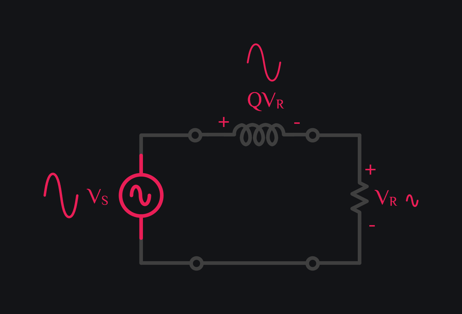
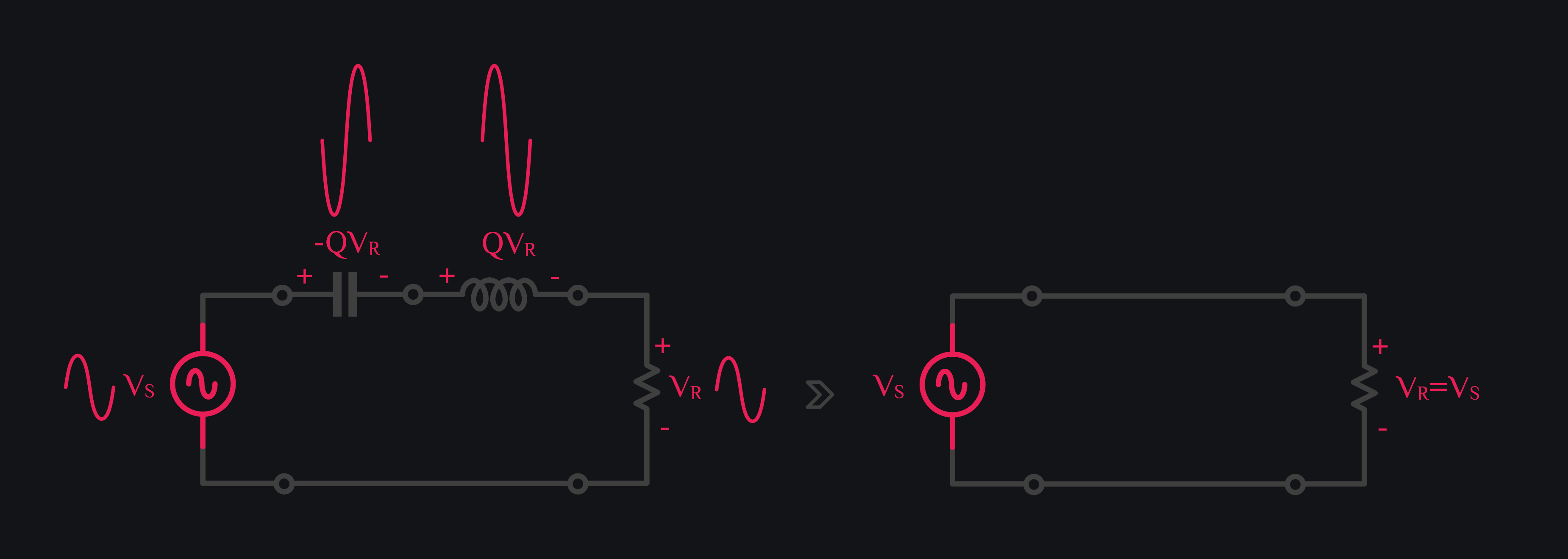
Nothing out of ordinary so far. VS got divided between R and X, and there was no amplification. Just the fact that voltage across inductor was Q times bigger than resistor. Magic happens when you insert a capacitor in series, and set this capacitor value to resonate the inductor out. That means if VS excites this circuit at resonance frequency, both inductor and capacitive reactance cancel out, and all of sudden your whole VS is dropped across resistor. Boom. Inductor voltage still has to be Q times bigger than resistor. Quality factor remains same. We did not do anything that could affect Q. We just added a capacitor. So there you go, your inductor still has QVR voltage which is equal to QVS (because now VR=VS), and that is voltage gain of Q! And not just inductor, capacitor has same reactance (with negative sign), so capacitor has voltage gain of Q as well (with opposite polarity). And of course it all makes sense because when you do KVL, inductor and capacitor voltage being out of phase (and they are always out of phase, resonance or not) cancel out, and your VS equals VR. So it is as if inductor and capacitor were never there, and yet there they are.
Intuition behind Voltage Gain
Your L & C needs a little charge to start forever oscillations, and you instead provided it with a VS source that keeps on adding energy to it in phase every cycle. As a result, voltage across L or C will blow up to infinity and beyond. You strategically placed a small resistor that keeps it from blowing up by taking whole VS across it. L & C no longer gets any more energy from VS, they retain their initial voltage across them which is QVS and keep bouncing that around back and forth.
How do we use this Voltage Gain?
You say, ok cool. Passives can really amplify but now how do we use it to our benefit. Can we really tap the amplified voltage across inductor? What kind of load can I connect? What is the driving capability of this inductor?
If you connect a load across inductor, it will lower the Q, and hence your gain! Therefore, you can only connect a high impedance load if you want to have some reasonable gain. So then we can say that it has very bad driving capability or it has no power gain (you see now why they were called passives), and no kidding nobody ever used these for amplification. So much so for quality factor and gain.
What do we do now? You may rest knowing passives cannot be used as amplifiers, and you didn’t miss out anything, and you go back to your life tinkering with transistors, and take pride in being analog IC designers. Or you will not settle for this. You will find a way out to grab this opportunity to use passive amplification. And guess what. Somebody already did. Somebody realized that this was the exact problem a matching network posed “Convert a small impedance (i.e, small voltage) to high impedance (i.e., high voltage)”, “No power gain needed. Just transform my impedance”. From there on, that somebody started distinguishing itself (a little) from Analog designers, and RF designers emerged out to this brave new world of matching impedances. And that’s the story of our unsung heroes.
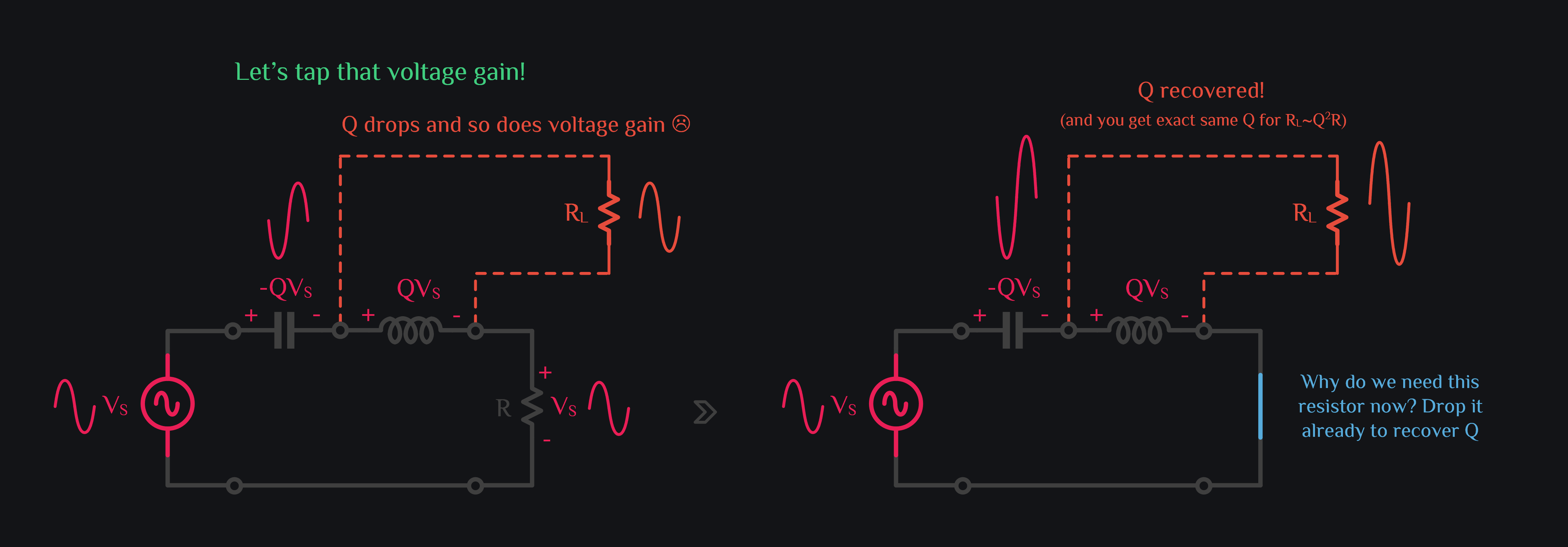
That is how we employ quality factor for signal gain. Now think about the circuit on right side in image above. What does it look like? It’s a matching network. We also secretly depicted in image above that if RL is Q2 times larger than R, Q remains same. This is a result of series to parallel transformation – a topic for next chapter.
P.S. Nothing against analog designers. Author is an analog designer too (well most of the times).
Browse by Tags
RFInsights
Published: 14 Feb 2023 (with love)
Last Edit: 21 Feb 2023