A Journey from Resonance to Impedance Matching
Chp. 4: Series to Parallel Conversion using Quality Factor
The Underrated Magic Trick
A series impedance can be transformed to equivalent parallel impedance and vice versa. This is the most underrated trick yet it is fundamental to matching network design. Math behind series to parallel conversion is simple. You want to know when a series impedance is equal to parallel impedance, so you equate them.
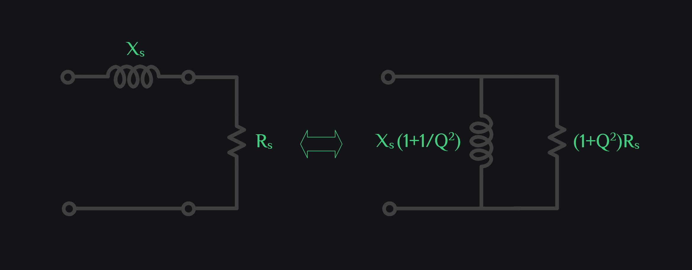
This means a resistor got boosted but reactance stayed same which is strange. Let’s explore the physical explanation of why is it so.
Intuition behind Series to Parallel Conversion
Excite a series RL circuit with voltage VS as shown in image below.
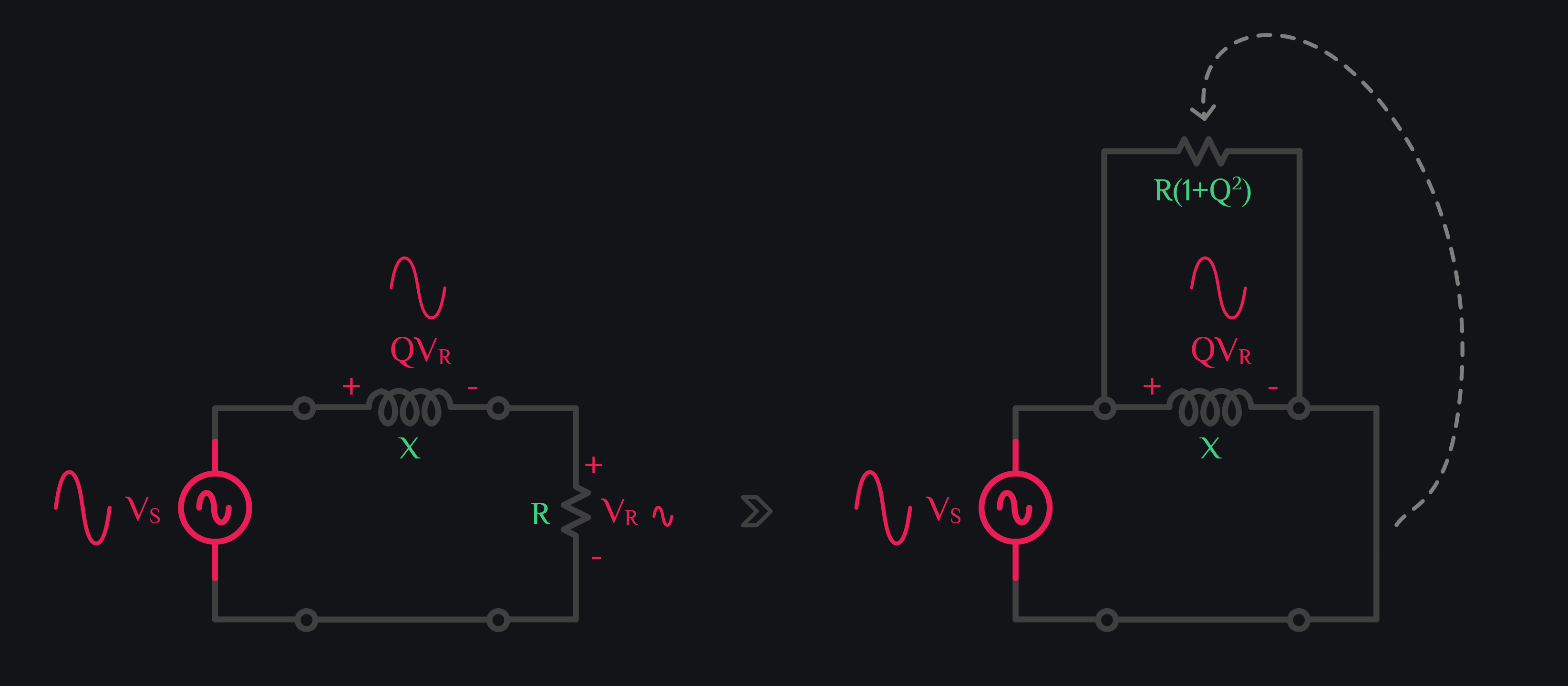
Power dissipated by resistor can be given as:
Physically it means voltage across R increased by factor Q. Remember in a series RL circuit, if a resistor has VR voltage, the inductor would have QVR voltage. Now when you move this resistor in parallel to inductor, resistor also taps a bigger voltage QVR. So if voltage goes up by Q, power goes by up Q2, therefore R also has to go up by Q2 to keep overall power same. Or you can say if voltage goes up by Q, current has to go down by Q to keep the power same (just like a transformer where if voltage goes up by turn ratio N, current goes down by N). So ratio \(\frac{QV}{\frac{I}{Q}}\) gives you \(Q^2\frac{V}{I}\) i.e., Q2 times higher impedance. Ok wait, you just said that it gets boosted by 1+Q2, and now you say Q2. Where did 1 go? To give you intuition behind boosting (i.e., resistor tapping a bigger voltage now), we said this bigger voltage is QVR but it is actually VS and that is almost equal to QVR for Q>>1 as revealed by Eq. (2). So, the factor 1 is there if you want to be very precise, but it wouldn’t be unfair to say Q is usually much greater than one, and to keep things simple (and memorable), we can just say impedance is boosted by Q2.
Why won’t inductor boost by factor Q2 as well?
Now that we argued that it makes sense for a series resistor to get boosted by factor Q2 when we place the resistor in parallel, you may ask why didn’t it happen to inductor because Eq. (1) tells us reactance stays almost same.
Let’s go back to series RL circuit. Inductor already had big voltage across it QVR. Going from series to parallel did not get it much bigger of voltage boost. It was QVR in series, and it is VS now in parallel. And as stated before, QVR is almost equal to VS for Q>>1. Therefore inductor value only has to go up a little to keep reactive power same. If inductor also gets a boost of Q2, it will draw huge reactive power, then we can’t say this parallel impedance is equal to series impedance because series inductor would have been drawing relatively small reactive power. And when Q is small, then yes boost in inductance is also visible. For Q>>1, you just don’t see much boost, so it is fair to say series and parallel reactance stays same.
Let’s run quick math to see this through. Reactive power across inductor in series RL circuit can be given as:
Is Series to Parallel Conversion Narrowband?
Note that a common misconception that exists is that this series to parallel impedance transformation is narrowband. The transformation itself is not narrow band, it is Q. Quality factor changes over frequency, and you need to update R and X values based on frequency. If you can do that, it is as wideband as you want. But you won’t be able to do that. Your typical case of use would be: you figured out what is parallel equivalent of your series circuit at one frequency, you went ahead and replaced that series circuit with parallel one. So that’s that. At that frequency, your series and parallel circuit would behave exactly same, at frequencies nearby their response would still be similar because Q wouldn’t have changed much, but once you start looking at far off frequencies, all bets are off because Q would have changed a lot.
Browse by Tags
RFInsights
Published: 18 Feb 2023
Last Edit: 18 Feb 2023