A Journey from Resonance to Impedance Matching
Chp. 2: Inductor vs Resonator Quality Factor
The Ultimate Truth Teller
The idea of quality factor originated from resonators and was ported to inductors later on. It was observed that a nice pure LC tank could not sustain oscillations because inductor degraded the quality of resonance. So instead of saying “bad” resonators, people started saying “bad” inductors and passed on the whole idea of quality to inductors. And so it began. Calculate inductors quality by taking ratio of imaginary to real part, and that would be the Q of inductor. It worked fine until it didn’t. Inductor started showing zero Q at their self-resonance frequency which was nor physical neither observable. You excite this inductor with impulse and you would see a damped sinusoidal response, exposing that it did have some quality, it did take some oscillations before the energy in inductor all died away. Then, why does our typical quality factor formula Q=R/X (for parallel circuit) give zero Q, and why do we keep using it? Let’s dive right into it.
When Inductor Quality Factor Formula Falls Apart
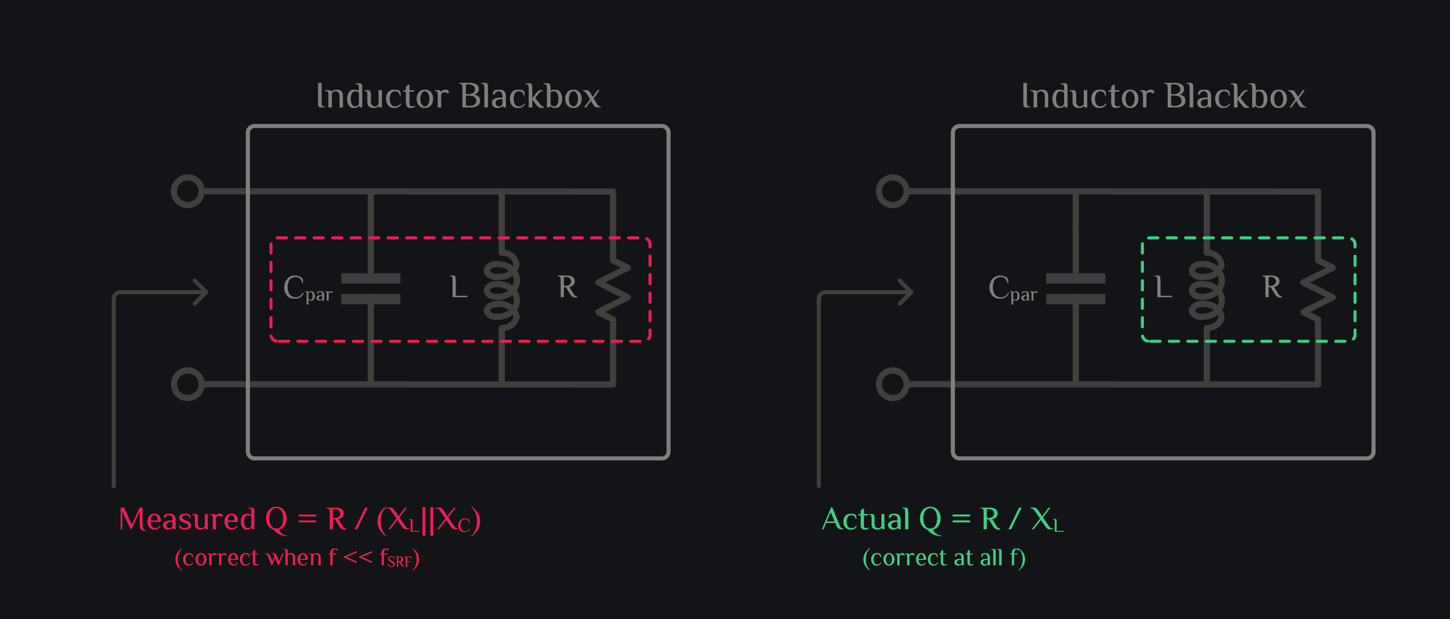
The definition of inductor quality factor Q=R/X implicitly assumes that inductor is free of parasitic capacitance, which is true at lower frequencies but does not hold at higher frequencies where capacitive reactance starts becoming “visible”. It substract from inductive reactance and makes overall imaginary part small. At resonance, both inductive and capacitive reactances are equal and opposite, thus net imaginary part is zero which makes our Q also zero. This is incorrect. Actual Q should be defined with imaginary part of just inductor or parasitic capacitor (one of them, not sum of them).
The problem is you don’t know how much imaginary part is coming from inductor, and how much from capacitor. You only get to measure the total overall imaginary, how should you find out real Q then? Go back where it all started: excite inductor with an impulse and measure the Q by using energy stored over energy lost formula of resonator.
Inductor vs Resonator Q
Let’s now compare Q based on two definitions.
Quality factor formula #1: Inductor Q (usual method)
Think of your inductor as parallel RLC. Q can be given as:
This method is inaccurate and leads to wrong Q at frequencies closer to self-resonance.
Quality factor formula #2: Resonator Q (the ultimate truth teller)
This is the ultimate test which gives the actual Q of the inductor. Excite your inductor with an impulse, run transient simulation and count how many cycles it takes for impulse response to die out. Q is approximately equal to those number of cycles. Or if you want to be more precise, follow the experiment below.
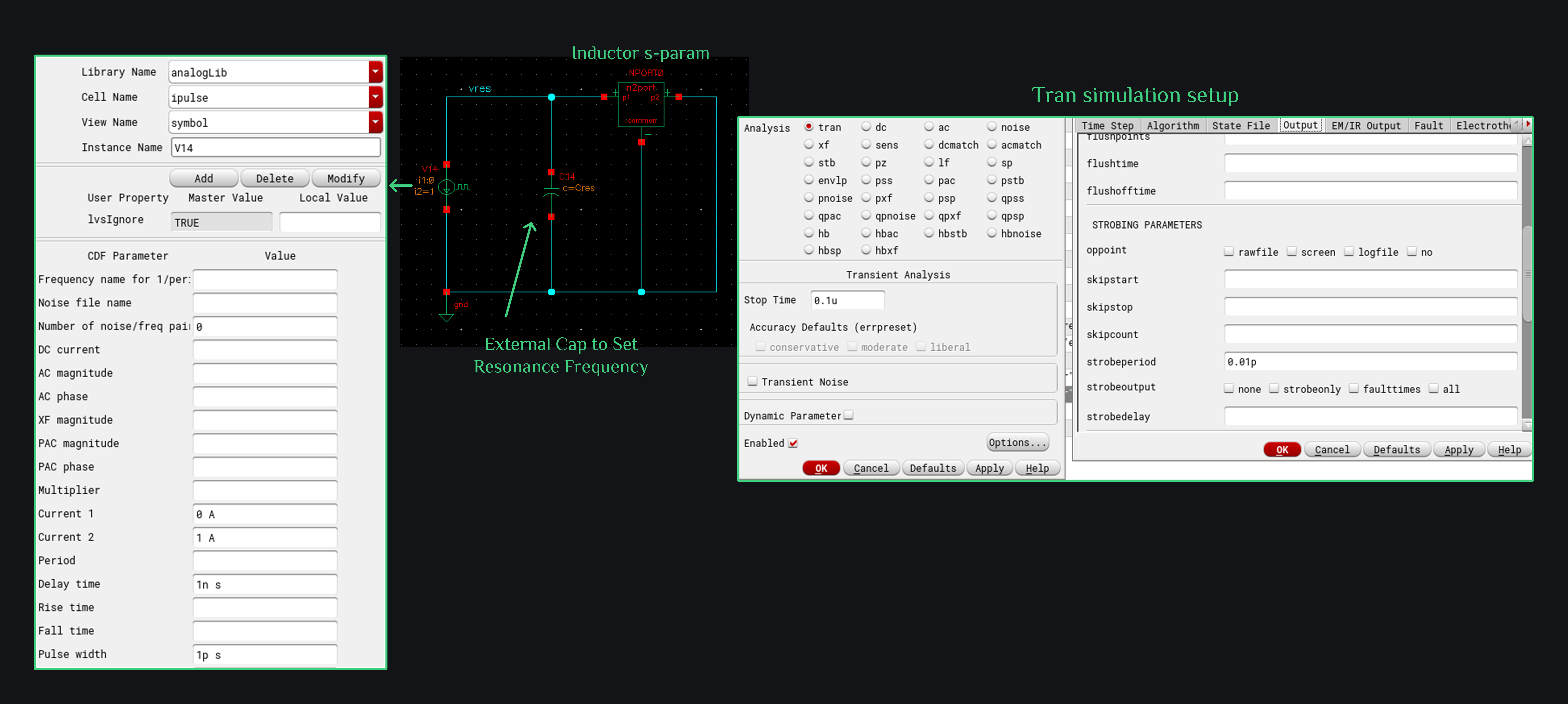
Simulation setup below consists of inductor 2-port s-param, a capacitor to set resonance frequency, and a current impulse which comes ON for 1pS with 1A current, and then turns off (turning off current source means open circuit, so now your inductor will die its natural death, meaning you will be able to see damped oscillations). Note that quality factor is defined at resonance (that’s where it all began), therefore we added an external cap to be able to sweep resonance frequency. So say you want to find out Q at 1GHz, you will set the cap in such a way that resonance frequency becomes 1GHz.
How do you find Q factor now? Remember we said that power left after each cycle can be given as:
where PS is power at start of a cycle and PL is power at end of a cycle.
By one cycle, we mean one oscillation of signal, and if voltage has oscillation frequency f, power being voltage square has twice the frequency, so two oscillations of power equals one cycle. This is demonstrated in the image below. We set external cap to zero so that inductor resonates at self-resonance frequency. Take any cycle. Measure power (or voltage squared) at its peak (30.49 V2 in image below). Measure power after one cycle (9.16 V2). Insert that in above formula and it gives 5.2 Q. You can also measure time period of one cycle and it gives out frequency of 8.2GHz, which says inductor SRF is 8.2GHz. (Does SRF match your s-param simulation, if yes, you tran simulation setup looks right)
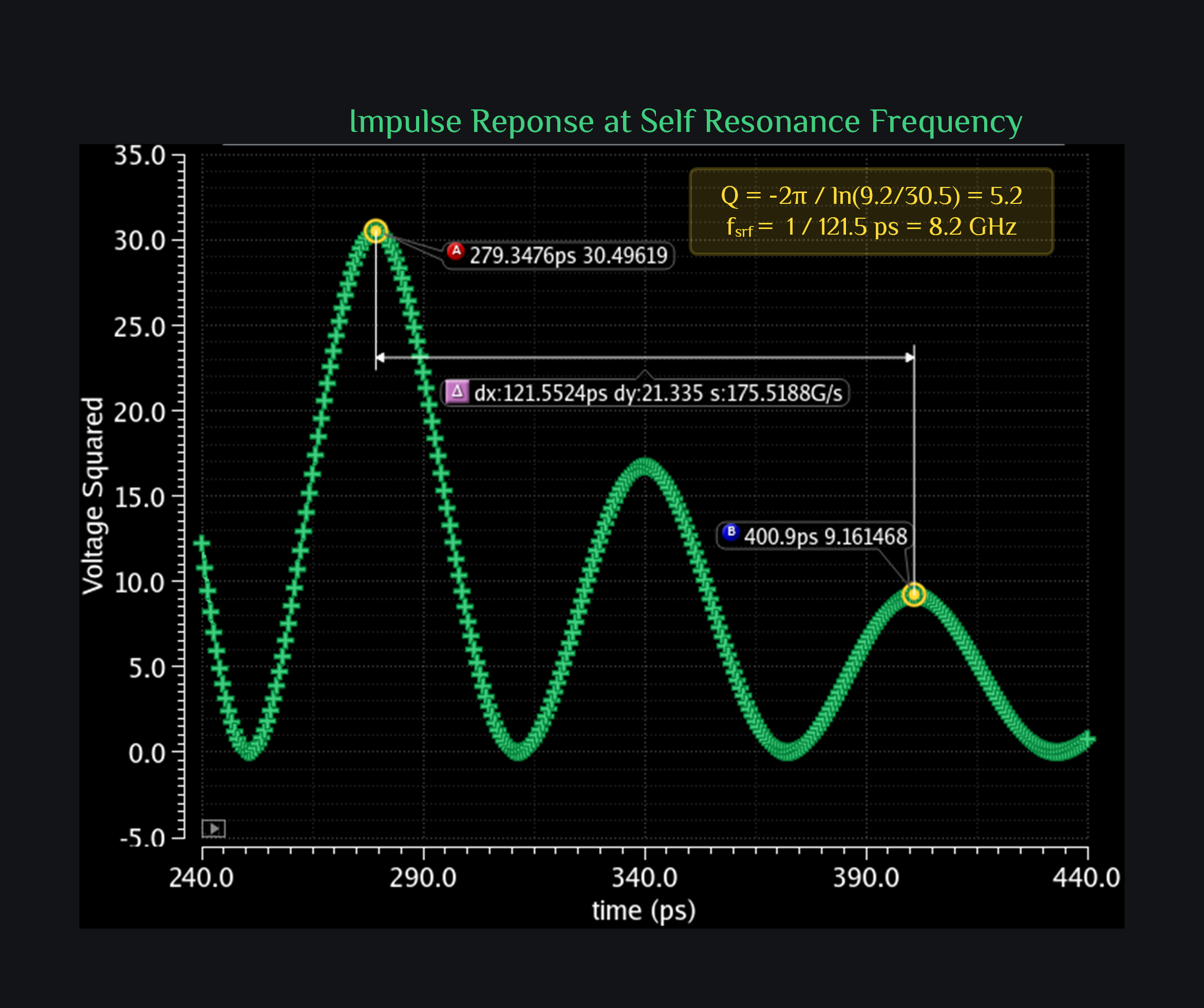
So this is interesting. This tells us even at resonance your inductor has finite Q whereas inductor Quality factor formula would have predicted a Q of zero.
Let’s compare over the frequency range now and see how Q looks like based on two definitions.
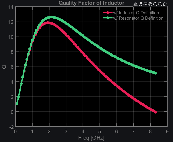
Q from inductor and resonator definition matches at low frequency. This makes sense because at these frequencies parasitic capacitance can be ignored and your regular definition of Q=X/R gives correct Q. As we increase frequency, Q start to differ and clearly falls apart near resonance frequency. Why do we keep on using Q=X/R definition? Because it is very easy to measure, and besides inductors are supposed to be used at frequencies lower than SRF, and there Q based on two definitions match. However, we can see even at frequencies much lower than SRF (look at 2GHz which is much lower than SRF of ~8GHz), resonator method gives slightly higher Q. So if correct value of Q is important (which it is), one should always check it with resonance method.
Honorable Mention
Remember we said the problem was separating out L & C reactance. If we can figure them out, we could compute the Q this way:
So then you might wonder, how about if I figure out L and C this way:
- Find L: At low frequencies, capacitors can be ignored and we are left with inductor and resistor. You can find L from here.
- Find C: Find self-resonance frequency (where imaginary part crosses zero). You already know L, you can find C using:
This may work and may not work based on inductor behavior over frequency. Our assumption here is that L does not change with frequency. We figured out the inductance value at low frequency, and used that in our Q formula. This is not correct because usually inductance would decrease with frequency. Why? Inductance is defined in a loop. The return path carries the current in opposite direction, creates magnetic field in opposite direction, thus cancelling out part of forward path magnetic field, thereby reducing inductance. This phenomena becomes more and more dominant at high frequencies where return path current is concentrated just underneath the forward path. At lower frequencies, the return path current is more spread out because it faces little inductances here and there and could just take more paths in ground plane to reach its destination. Therefore, L is different at low and high frequencies. If L would have kept itself constant over frequency, you could used this method.
Browse by Tags
RFInsights
Published: 13 Feb 2023
Last Edit: 26 June 2025