Are you running FFT on time domain signaland need to have a brick-wall low pass filter to remove aliasing? Are you debugging non-linearities like IM3 and want to filter out certain harmonics to see what were their contribution? You need reconfigurable ideal filters. These are top three options in Cadence to quickly build any kind of filter, we discuss them in context of low pass filter.
1. Ideal Filter in rfLib
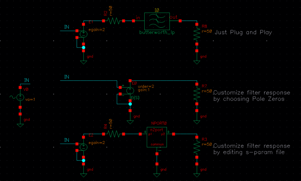
Cadence rfLib (InstallDIR/tools/dfII/samples/artist/rfLib) has butterworth_lp filter (along with hp, bp etc. options) which can be set to as high as \(20^{th}\) order which is good enough to serve as brick-wall filter. If you feel like you need an even higher order filter, you can cascade these filters. This filter needs to be terminated with 50 Ω input and output impedance. At input it will form a voltage divider by 2, therefore we also add vcvs source of gain 2 as shown in image above.
2. svcvs in analogLib
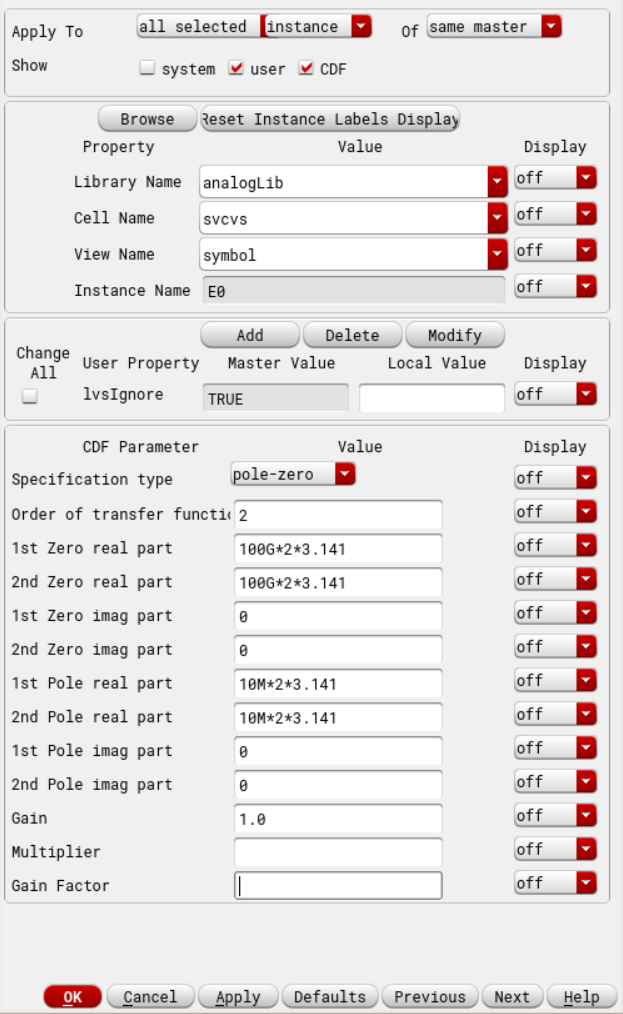
Cadence analogLib has svcvs source which is a frequency dependent voltage controlled voltage source. Its frequency dependence can be set by either polynomial coefficients or using poles and zeros. Image below shows how to setup a 2nd order 10MHz low pass filter using poles and zeros. Note that in low pass filter, zeros are at infinity, therefore we set real part of zeros to be at 100GHz. Also note that by default it will use 1 in fields, so we need to explicitly set imaginary part to zero.
3. nport in analogLib
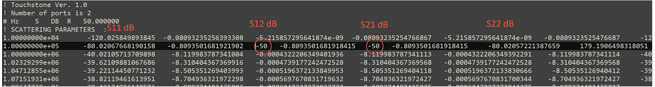
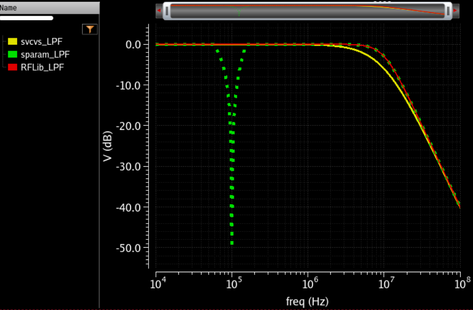
You can use above methods, run sp simulation in Cadence to export an s-param file. Once you have this file, you can edit it as you like. For example, I wanted to add -50dB notch at 100kHz to my 10MHz low pass filter. Image below shows I changed S21 and S12 to -50 for 100kHz frequency in this file. Now we can use nport in analogLib in Cadence, import this edited file and run whatever simulation we are interested in. I ran AC simulation and you do see a dip at 100kHz (green plot below). How cool. One tip here though is that these s-param files usually have trouble in transient simulations, make sure the dip that you added has some width or looks closer to a real system. If you just add a dip at one frequency, and immediately right after that frequency say you go back to 0dB attenuation, my guess is it will start throwing different warnings like maybe passivity violation or non-causal or interpolation error etc.
Author: RFInsights
Date Published: 18 Sep 2022
Last Edit: 01 Feb 2023