Integrated Transformer Models
We decided to write this article because there are only so many different models of a transformer that exist. Analog IC designers, RFIC designers and mm-wave IC designers – they all understand transformers a little differently. Enough is enough. We are putting together a list of different models (with derivations of course) for your quick reference, and we also show you THE one favored by the most folks.
Integrated Transformer Model # 1 – Base Model
Consider a transformer as shown in image below.
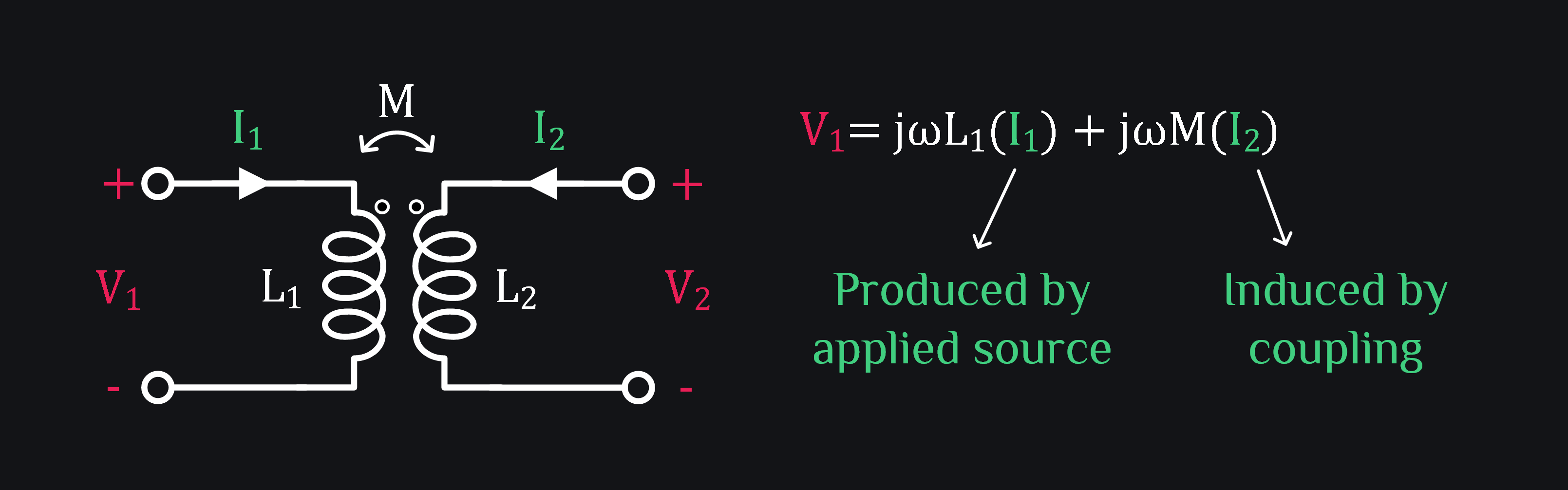
Applied source V1 consists of two voltage drops: First, the voltage drop produced by the current I1 which is generated from the V1 itself. And second, the voltage drop produced by induced current I2 which is actually generated by V2. Therefore, we can write V1 and V2 as:
or
Recall that this looks much like a 2-port Z-parameter matrix given as:
Therefore, we can say:
The equivalent circuit for Z-parameters of a reciprocal 2-port network can be given as:
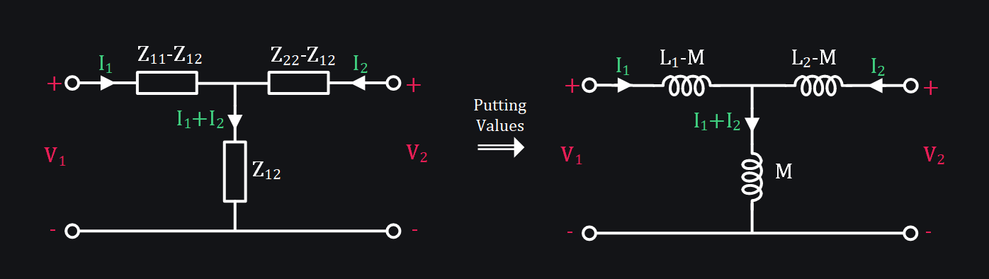
This is the base model of a transformer. It says, if I2 were zero (i.e., secondary is open-circuited), then applying V1 and measuring I1 will only reveal L1 (which makes sense as primary inductance is L1). However, the moment you apply some V2, mutual inductance M will lead to slightly different I1, thus V1/I1 will no longer give you L1 impedance. It will be different. What shall it be? Let’s improve this base model to answer such questions. Before that, let’s get done with some FAQs.
FAQs
Q: What is difference between M and k?
A: M is real deal. M is real physical thing. M is mutual inductance which is a way of saying how much “extra” voltage is produced in one coil due to magnetic field “coupling” created by I2 in second coil. k is just a way of saying coupling is not perfect.
Q: Define M
A: \(M=\sqrt{L_1L_2}\)
Q: Define k
A: k is saying hey this M is going to be less than its value because coupling ain’t good so you’d better write M as \(M=k\sqrt{L_1L_2}\) where \(0 \le k \le1 \)
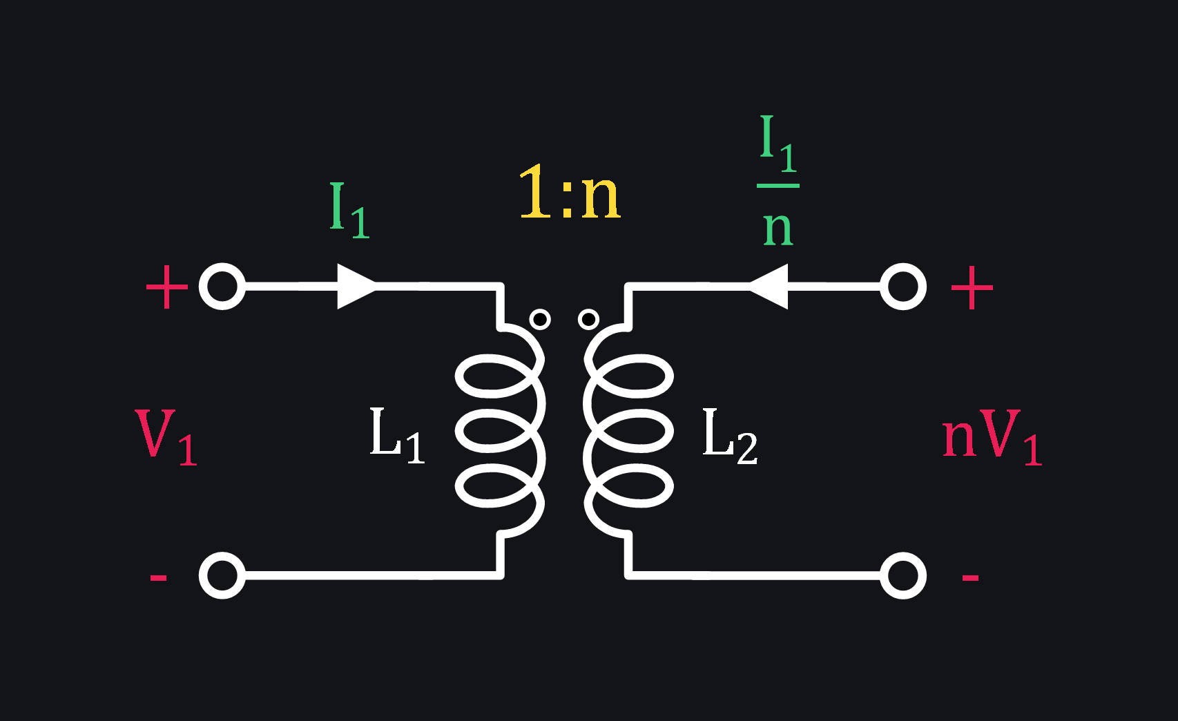
Q: Base transformer model shown above didn’t talk about turn ratio. How to think of turn ratio?
A: Consider an ideal transformer with turn ratio (N2/N1) as n
Practical transformer: Hey coupling ain’t perfect, so terminal relations of Eq. (2) won’t hold. Add k.
Integrated Transformer Model # 2 – add Turn Ratio
People would like to separate out turn ratio and keep it as a clear visible metric to quickly transform impedance. So you won’t see the base model being used anywhere at least in IC design.
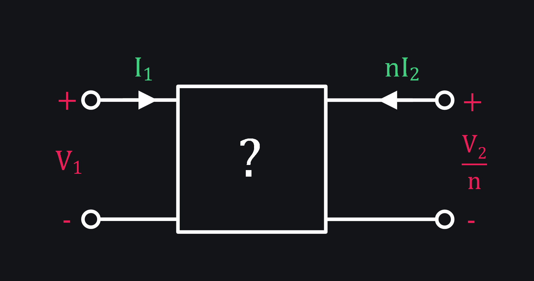
What do people want? A model like this:
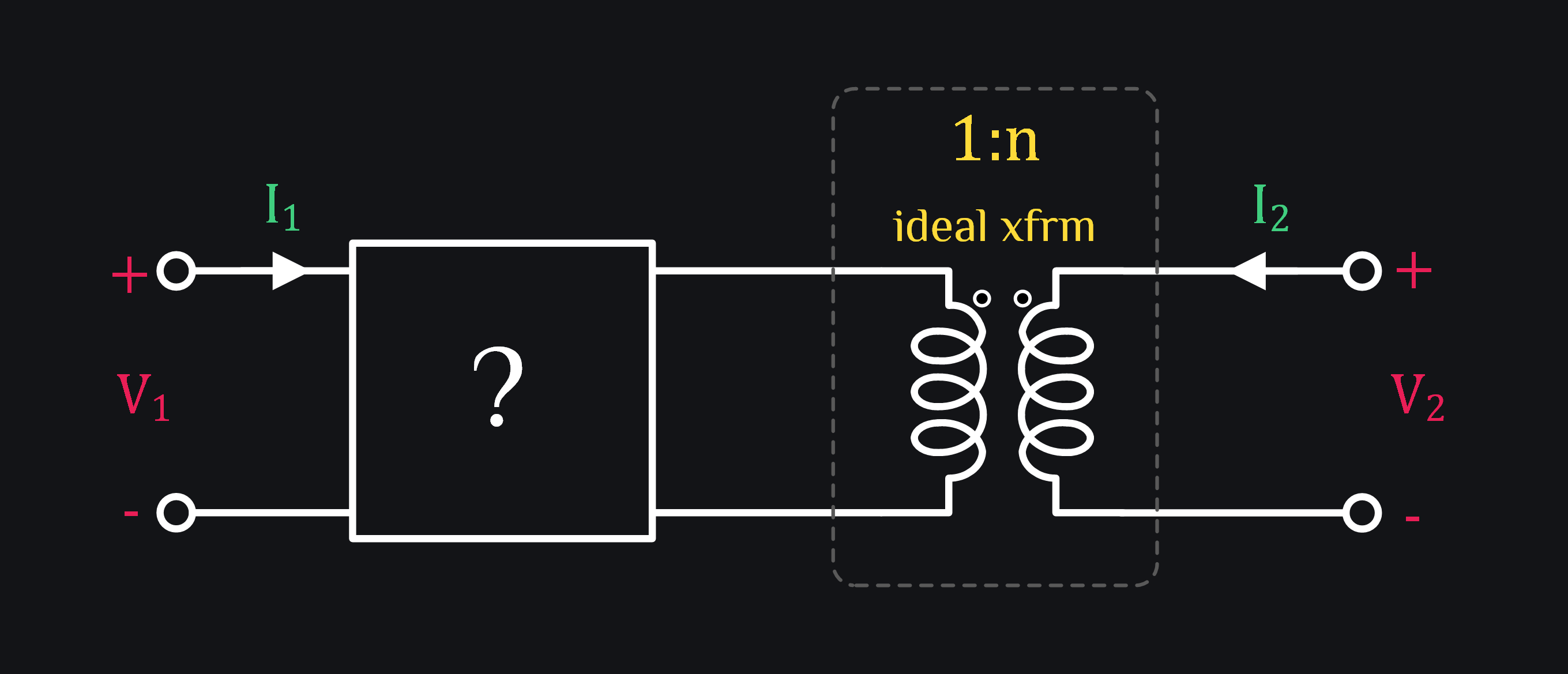
Think about the terminal relations of the black box ? now. They are:
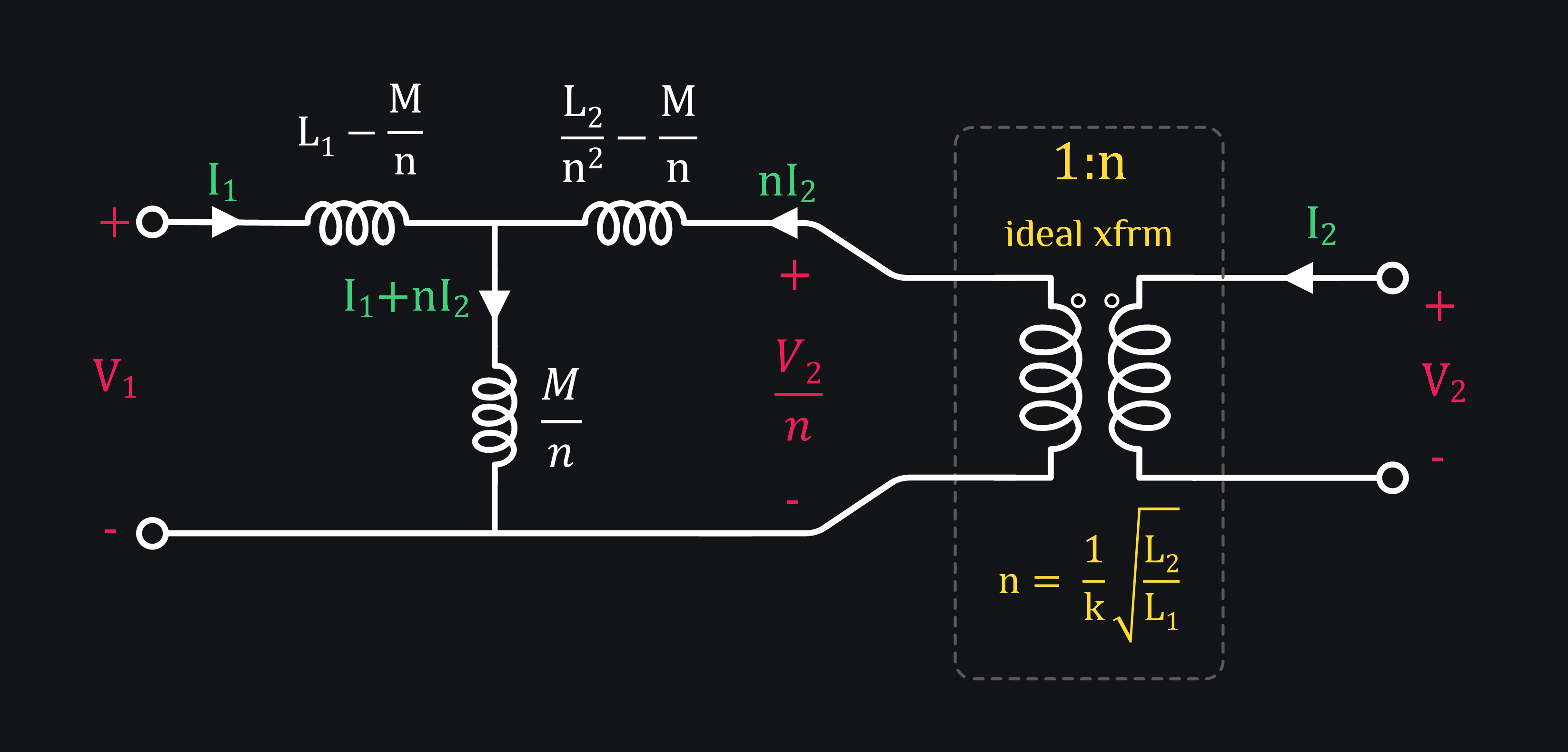
We want to know what kind of transformer can we put here which in series with ideal transformer of 1:n would produce same results as original transformer. Start with writing the z-matrix:
Comparing it with Eq. 1 gives us:
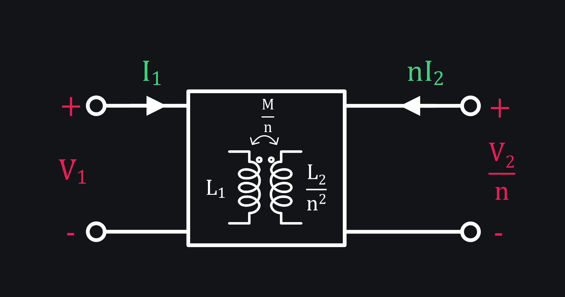
This says our black box is actually a transformer like this:
Integrated Transformer Model # 3 – We don’t like M
Engineers just wouldn’t like to see M. They work with k. So let’s get rid of M, ready when you are.
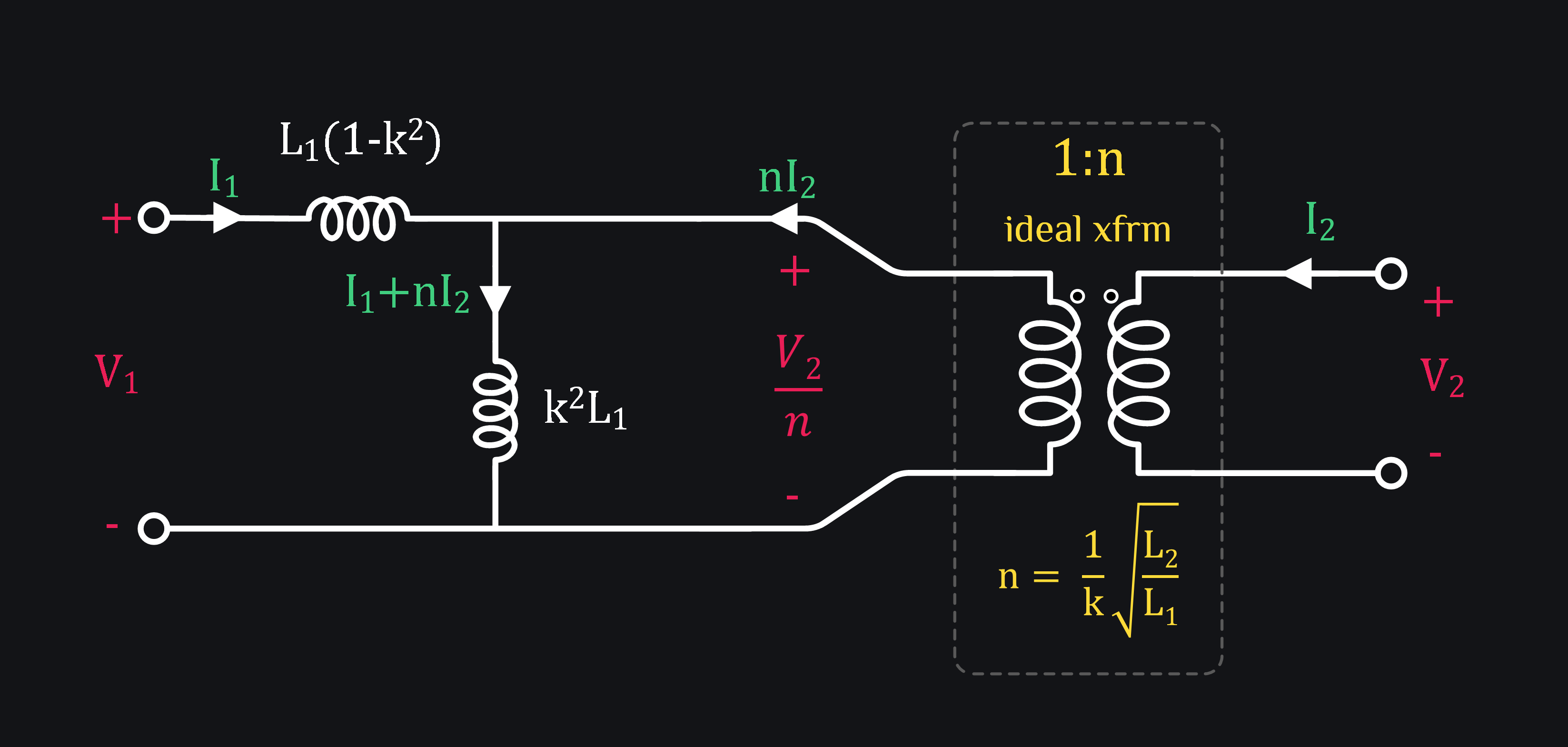
- L1(1-k2) represents drop across “leakage inductance”. It says all of your V1 won’t reach transformer primary because k wasn’t perfect.
- k2L1 represents magnetization inductance because voltage that reached to it is actually what create magnetic fields.
Interesting insights we must say, hey we are not bragging, we are just happy to refresh these insights ourselves.
Integrated Transformer Model # 4 – Where’s my L2
Some folks are destined to lose it the first time they see above model of transformer. They go like “but where is the secondary inductor (L2) of transformer, it seems L1 is all mighty, does that mean L2 not matter at all? because it’s definitely not in the model”. While it’s not visible, it’s hidden in k and n. Therefore, some folks would use the model shown below (fourth model) where they can clearly see their beloved L2.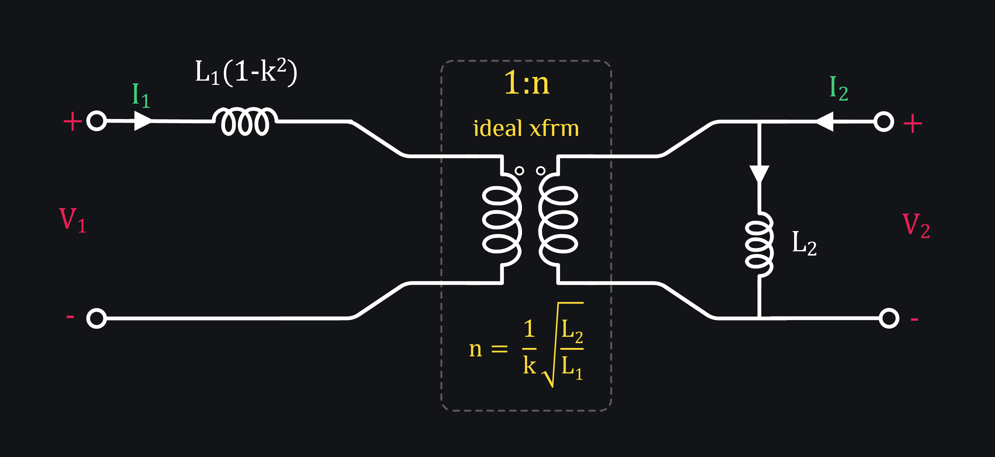
It’s not hard to prove that k2L1 on primary side becomes L2 when moved to secondary. Just multiply k2L1 by n2 (because remember an ideal transformer transforms impedance by n2)
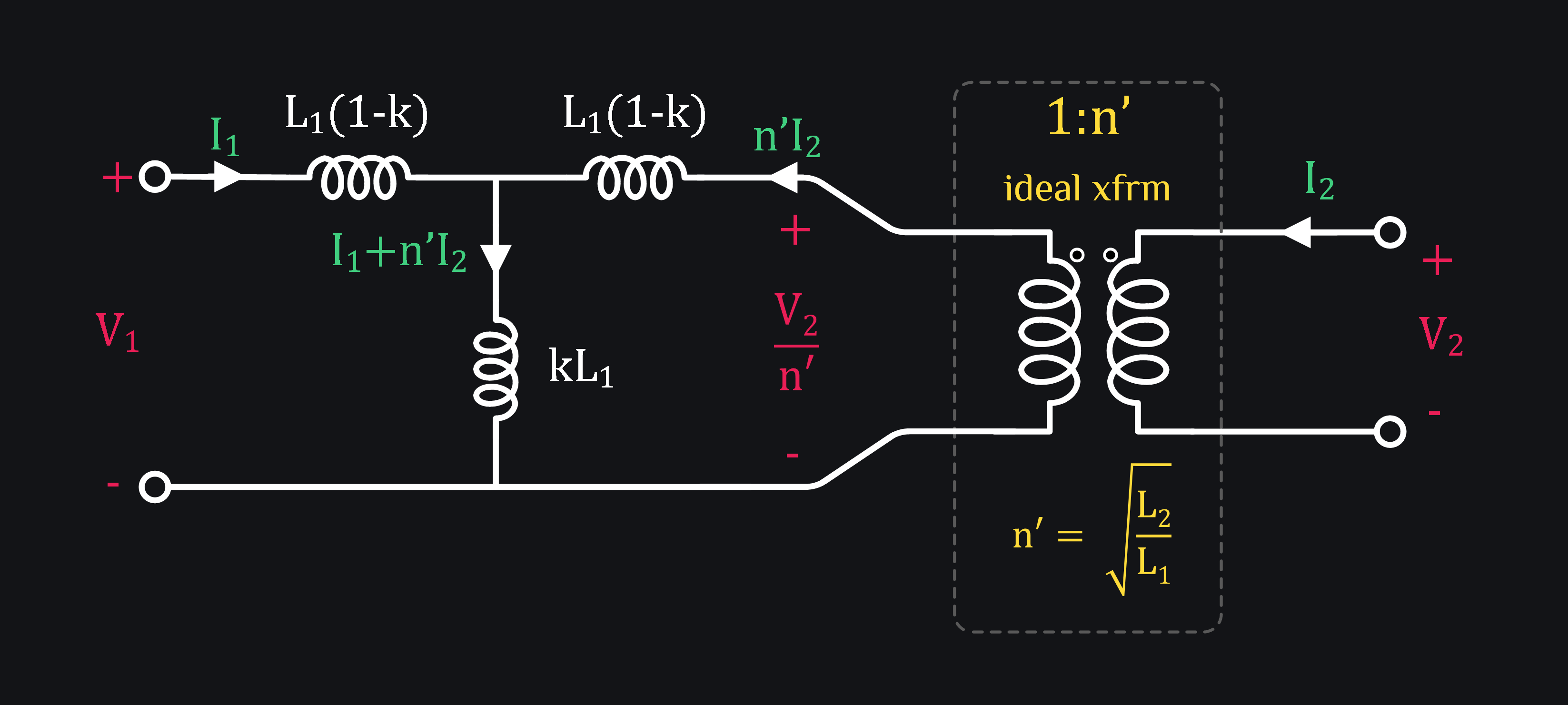
Integrated Transformer Model # 5 – Just to Cover the Ground
There is yet another genre of folks who just don’t like to see k in their turn ratio n. It is more intuitive for them to think: “hmm that’s how I need to size my L1 and L2 to get this turn ratio n”, whatever k does, it does. We will model it separately. Oh well. Okay. So let’s try to take k out of n and see how our model looks like.
We know from Eq. (3) that
We covered all the transformer models we have encountered so far. Out of all these, we recommend to start with model # 3, and keep others in mind just to build intuition. It all depends on ease of you. Maybe some other model is easier to use for your situation.
Here’s a quick summary of why \( M = \sqrt{L_1L_2} \) for nerdy you.
RFInsights
Date Published: 01 Jan 2023
Last Edit: 28 Jun 2023