RFIC Design

RFInsights

TX HRM Mixer

Your mixer has two frequencies going in, \(\omega_{bb}\) and \(\omega_{lo}\), and you desire only one frequency coming out, \(\omega_{lo}+\omega_{bb}\). With the risk of stating the obvious, that is not what happens in real world. Your mixer outputs a lot more trash than you would have ever imagined. Some of it lies far away from your desired signal and can be filtered out (and even here is a catch: filter block might come very late in TX like you may have driver or power amplifiers before you finally make it to your output; chances are damage is already done), and  some lies close enough that you need circuit techniques to get rid of them.  In either case, your best bet is to nip the evil in the bud: kill the undesired products right away where they are generated before this cancer spreads everywhere. LO harmonics are some of the nasty trashy products that make it to your TX output. Even if you have everything ideal in your TX, the hard switching nature of mixer would get you \(n\omega_{lo}+\omega_{bb}\) at its output, which means you will have a copy of your signal sitting at each harmonic of LO at TX output. Harmonic rejection is a technique to get rid of all the undesired LO harmonics, and by undesired, we mean literally all of them except n=1. We will look at 4-phase TX HRM Mixer which will cancel 3rd and 5th harmonics of LO, and 4FMODs as an added advantage.

TX Harmonic Reject Mixer

TX HRM Mixer – Math & Insights

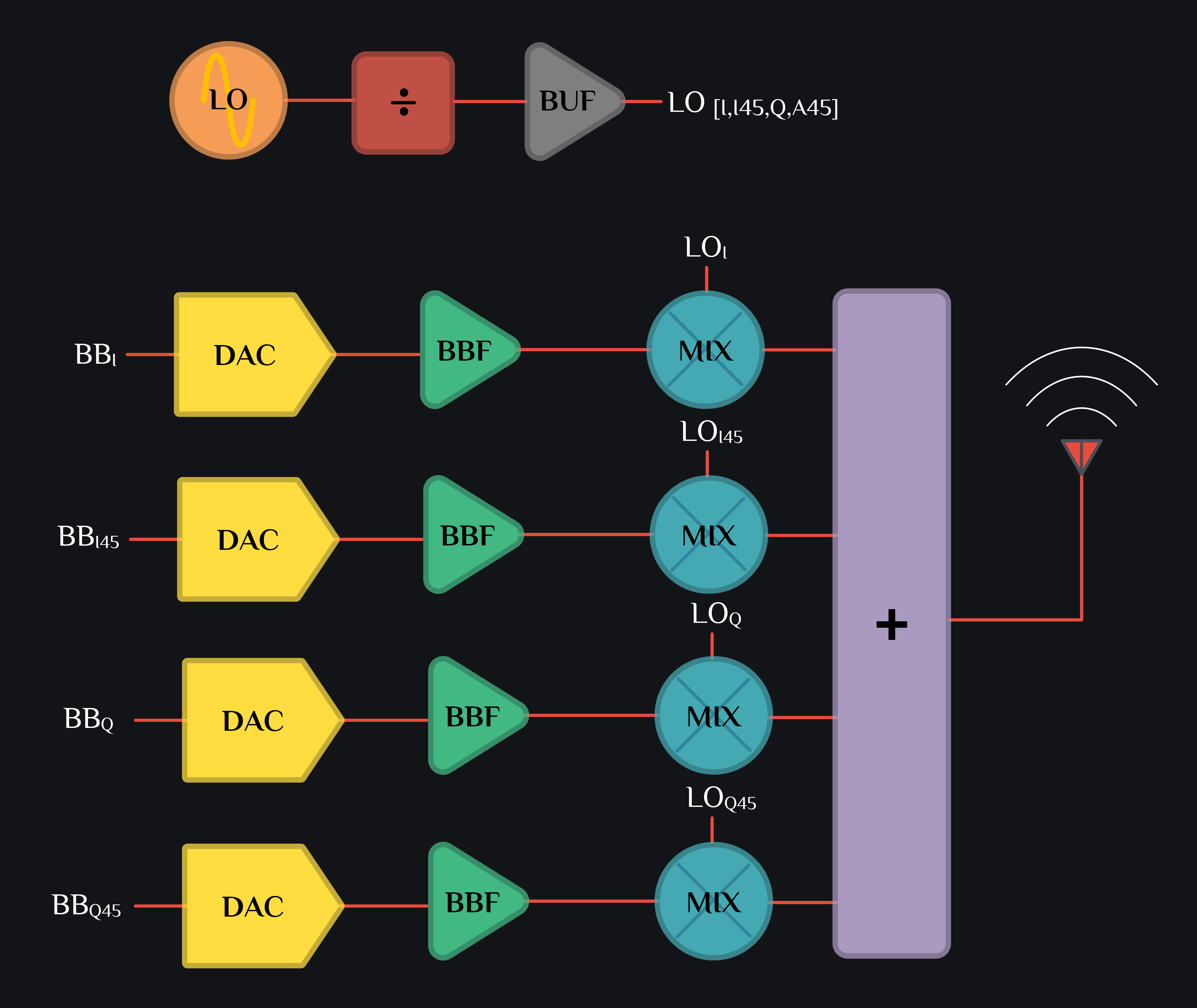
Consider an HRM TX as shown in image above. I channel DAC generates cosine signal, I45 channel DAC generates 0.125 \(T_{bb}\) shifted version of I channel, Q channel DAC generates 0.25 \(T_{bb}\) shifted version of I channel and Q45 DAC generates 0.375 \(T_{bb}\) shifted version of I channel:

\begin{alignat*}{8} \\ DAC:\,& I(t) &=&\, Vcos\,(\omega_{bb}\,t)\\ DAC:\,& I45(t) &=&\, Vcos\,(\omega_{bb}\,t - \frac{\pi}{4})\\ DAC:\,& Q(t) &=&\, Vcos\,(\omega_{bb}\,t - \frac{\pi}{2})\\ DAC:\,& Q45(t) &=&\, Vcos\,(\omega_{bb}\,t - \frac{3\pi}{4})\\ \end{alignat*}
These signals pass through some baseband circuit, say a baseband amplifier which adds 3rd & 5th order non-linearity. Signal at baseband amplifier output can be written as:
\begin{alignat*}{8} \\ BBF:\,& I(t) &=&\, \textcolor{#40ce80}{A_1\,cos(\omega_{bb}\,t)}+\textcolor{#feda39}{A_3\,cos(3\omega_{bb}\,t)}+\textcolor{#e74c3c}{A_5\,cos(5\omega_{bb}\,t)}\\ BBF:\,& I45(t) &=&\, A_1\,cos(\omega_{bb}\,t -\frac{\pi}{4})+A_3\,cos(3\omega_{bb}\,t-\frac{3\pi}{4})+A_5\,cos(5\omega_{bb}\,t-\frac{5\pi}{4})\\ & &=&\, \textcolor{#40ce80}{A_1\,cos(\omega_{bb}\,t-\frac{\pi}{4})}+\textcolor{#feda39}{A_3\,sin(3\omega_{bb}\,t-\frac{\pi}{4})}-\textcolor{#e74c3c}{A_5\,sin(5\omega_{bb}\,t+\frac{\pi}{4})}\\ BBF:\,& Q(t) &=&\, A_1\,cos(\omega_{bb}\,t -\frac{\pi}{2})+A_3\,cos(3\omega_{bb}\,t-\frac{3\pi}{2})+A_5\,cos(5\omega_{bb}\,t-\frac{5\pi}{2})\\ & &=&\, \textcolor{#40ce80}{A_1\,sin(\omega_{bb}\,t)}-\textcolor{#feda39}{A_3\,sin(3\omega_{bb}\,t)}+\textcolor{#e74c3c}{A_5\,sin(5\omega_{bb}\,t)}\\ BBF:\,& Q45(t) &=&\, A_1\,cos(\omega_{bb}\,t -\frac{3\pi}{4})+A_3\,cos(3\omega_{bb}\,t-\frac{9\pi}{4})+A_5\,cos(5\omega_{bb}\,t-\frac{15\pi}{4})\\ & &=&\, \textcolor{#40ce80}{A_1\,sin(\omega_{bb}\,t-\frac{\pi}{4})}+\textcolor{#feda39}{A_3\,cos(3\omega_{bb}\,t-\frac{\pi}{4})}+\textcolor{#e74c3c}{A_5\,cos(5\omega_{bb}\,t+\frac{\pi}{4})}\\ \end{alignat*}

where \(A_{1}\) is a linear gain coefficient, \(A_{3}\) is 3rd order distortion coefficient and \(A_{5}\) is 5th order distortion coefficient. Read more on single tone distortion here. Image below shows our sinusoids look little distorted (we assume \(A_{1}=1\), \(A_{3}=0.1\) and \(A_{5}=0.05\)) once they come out of BBF. Access these plots here.

Consider an LO signal now. I channel LO is a square wave toggling between +/- 1, I45 channel LO  is 0.125 \(T_{bb}\) shifted copy of I channel, Q channel LO is 0.25 \(T_{bb}\) shifted copy of I channel and Q45 LO is 0.375 \(T_{bb}\) shifted copy of I channel. Note that we do not say phase shifted rather time shifted. This distinction is important. A time shifted signal means each harmonic of that signal will get phase shifted proportional to frequency. We need this for HRM magic to work.

Developing only up to 5th harmonic of square wave, LO signals can be written as:
\begin{alignat*}{8} \\ LO:\,& I(t) &=&\, \textcolor{#FFFFFF}{\frac{4}{\pi}\left[cos(\omega_{lo}\,t)-\frac{1}{3}cos(3\omega_{lo}\,t)+\frac{1}{5}cos(5\omega_{lo}\,t)\right]}\\ LO:\,& I45(t) &=&\, \frac{4}{\pi}\left[cos(\omega_{lo}\,t-\frac{\pi}{4})-\frac{1}{3}cos(3\omega_{lo}\,t-\frac{3\pi}{4})+\frac{1}{5}cos(5\omega_{lo}\,t-\frac{5\pi}{4})\right]\\ & &=&\, \textcolor{#FFFFFF}{\frac{4}{\pi}\left[cos(\omega_{lo}\,t-\frac{\pi}{4})-\frac{1}{3}sin(3\omega_{lo}\,t-\frac{\pi}{4})-\frac{1}{5}sin(5\omega_{lo}\,t+\frac{\pi}{4})\right]}\\ LO:\,& Q(t) &=&\, \frac{4}{\pi}\left[cos(\omega_{lo}\,t-\frac{\pi}{2})-\frac{1}{3}cos(3\omega_{lo}\,t-\frac{3\pi}{2})+\frac{1}{5}cos(5\omega_{lo}\,t-\frac{5\pi}{2})\right]\\ & &=&\, \textcolor{#FFFFFF}{\frac{4}{\pi}\left[sin(\omega_{lo}\,t)+\frac{1}{3}sin(3\omega_{lo}\,t)+\frac{1}{5}sin(5\omega_{lo}\,t)\right]}\\ LO:\,& Q45(t) &=&\, \frac{4}{\pi}\left[cos(\omega_{lo}\,t-\frac{3\pi}{4})-\frac{1}{3}cos(3\omega_{lo}\,t-\frac{9\pi}{4})+\frac{1}{5}cos(5\omega_{lo}\,t-\frac{15\pi}{4})\right]\\ & &=&\, \textcolor{#FFFFFF}{\frac{4}{\pi}\left[sin(\omega_{lo}\,t-\frac{\pi}{4})-\frac{1}{3}cos(3\omega_{lo}\,t-\frac{\pi}{4})-\frac{1}{5}sin(5\omega_{lo}\,t+\frac{\pi}{4})\right]}\\ \end{alignat*}

Image below shows LO signals. We see ringing because we only added up to 5 harmonics of LO. That also gives you an idea that if you assume 5 harmonics, your LO still does not look quite much like square wave, so consider analyzing/adding more harmonics when you are debugging needles in a haystack.

I channel baseband signal is multiplied by I channel LO, I45 with I45, Q with Q, Q45 with Q45 and they are all summed up. We can write mixer output as:

$$ MIXER:\; I_{BBF}\,(t).I_{LO}\,(t)+I45_{BBF}\,(t).I45_{LO}\,(t)+Q_{BBF}\,(t).Q_{LO}\,(t)+Q45_{BBF}\,(t).Q45_{LO}\,(t)$$

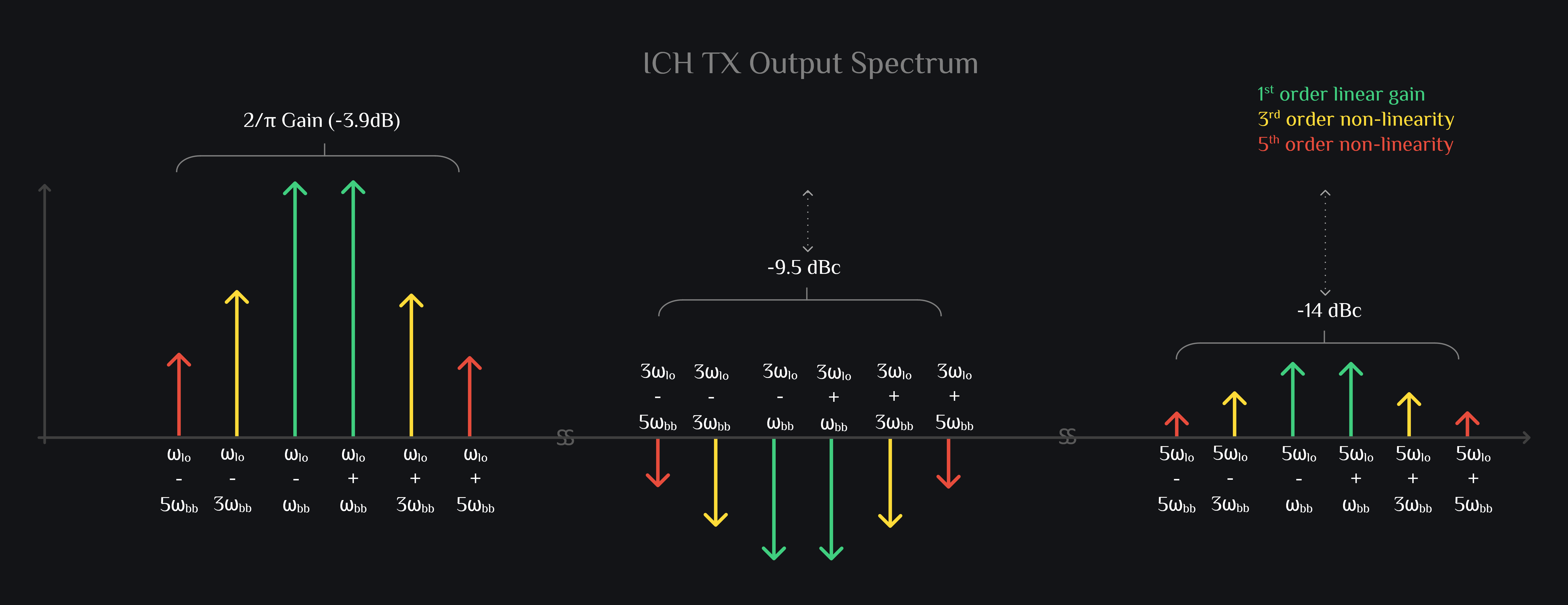
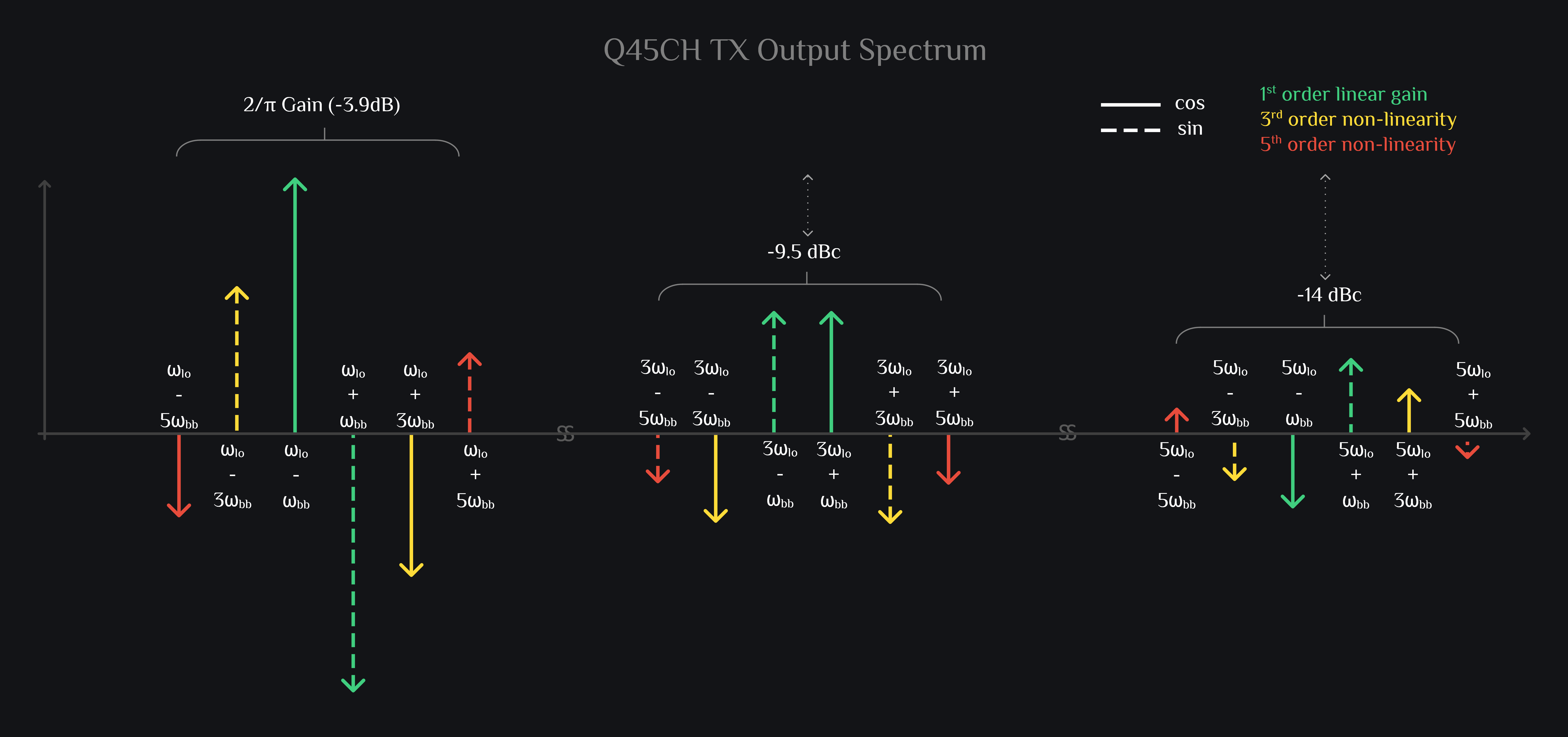
I Channel Mixer Output

\[ \left[ \textcolor{#40ce80}{A_1\,\textcolor{#40ce80}{cos(\omega_{bb}\,t)}}+\textcolor{#feda39}{A_3\,\textcolor{#feda39}{cos(3\omega_{bb}\,t)}}+\textcolor{#e74c3c}{A_5\,\textcolor{#e74c3c}{cos(5\omega_{bb}\,t)}} \right]. \left[ \textcolor{#FFFFFF}{\frac{4}{\pi}\textcolor{#FFFFFF}{cos(\omega_{lo}\,t)}-\frac{1}{3}\textcolor{#FFFFFF}{cos(3\omega_{lo}\,t)}+\frac{1}{5}\textcolor{#FFFFFF}{cos(5\omega_{lo}\,t)}}\right]\\ \] \begin{alignat*}{8} \\ =\frac{4}{\pi} \biggr[ & \textcolor{#40ce80}{A_1cos(\omega_{bb}\,t)}.\textcolor{#FFFFFF}{cos(\omega_{lo}\,t)}\;&-&\;\frac{\textcolor{#40ce80}{A_1}}{\textcolor{#FFFFFF}{3}}\textcolor{#40ce80}{cos(\omega_{bb}\,t)}.\textcolor{#FFFFFF}{cos(3\omega_{lo}\,t)}\;&+&\;\frac{\textcolor{#40ce80}{A_1}}{\textcolor{#FFFFFF}{5}}\textcolor{#40ce80}{cos(\omega_{bb}\,t)}.\textcolor{#FFFFFF}{cos(5\omega_{lo}\,t)}\\ +& \textcolor{#feda39}{A_3cos(3\omega_{bb}\,t)}.\textcolor{#FFFFFF}{cos(\omega_{lo}\,t)}\;&-&\;\frac{\textcolor{#feda39}{A_3}}{\textcolor{#FFFFFF}{3}}\textcolor{#feda39}{cos(3\omega_{bb}\,t)}.\textcolor{#FFFFFF}{cos(3\omega_{lo}\,t)}\;&+&\;\frac{\textcolor{#feda39}{A_3}}{\textcolor{#FFFFFF}{5}}\textcolor{#feda39}{cos(3\omega_{bb}\,t)}.\textcolor{#FFFFFF}{cos(5\omega_{lo}\,t)}\\ +& \textcolor{#e74c3c}{A_5cos(5\omega_{bb}\,t)}.\textcolor{#FFFFFF}{cos(\omega_{lo}\,t)}\;&-&\;\frac{\textcolor{#e74c3c}{A_5}}{\textcolor{#FFFFFF}{3}}\textcolor{#e74c3c}{cos(5\omega_{bb}\,t)}.\textcolor{#FFFFFF}{cos(3\omega_{lo}\,t)}\;&+&\;\frac{\textcolor{#e74c3c}{A_5}}{\textcolor{#FFFFFF}{5}}\textcolor{#e74c3c}{cos(5\omega_{bb}\,t)}.\textcolor{#FFFFFF}{cos(5\omega_{lo}\,t)} \biggr] \\ \\ =\frac{2}{\pi} \biggr[ & \textcolor{#40ce80}{A_1\{cos(\omega_{lo}-\omega_{bb})t+cos(\omega_{lo}+\omega_{bb})t\}}\;&-&\;\textcolor{#40ce80}{\frac{A_1}{3}\{cos(3\omega_{lo}-\omega_{bb})t+cos(3\omega_{lo}+\omega_{bb})t\}}\;&+&\;\textcolor{#40ce80}{\frac{A_1}{5}\{cos(5\omega_{lo}-\omega_{bb})t+cos(5\omega_{lo}+\omega_{bb})t\}}\\ +& \textcolor{#feda39}{A_3\{cos(\omega_{lo}-3\omega_{bb})t+cos(\omega_{lo}+3\omega_{bb})t\}}\;&-&\;\textcolor{#feda39}{\frac{A_3}{3}\{cos(3\omega_{lo}-3\omega_{bb})t+cos(3\omega_{lo}+3\omega_{bb})t\}}\;&+&\;\textcolor{#feda39}{\frac{A_3}{5}\{cos(5\omega_{lo}-3\omega_{bb})t+cos(5\omega_{lo}+3\omega_{bb})t\}}\\ +& \textcolor{#e74c3c}{A_5\{cos(\omega_{lo}-5\omega_{bb})t+cos(\omega_{lo}+5\omega_{bb})t\}}\;&-&\;\textcolor{#e74c3c}{\frac{A_5}{3}\{cos(3\omega_{lo}-5\omega_{bb})t+cos(3\omega_{lo}+5\omega_{bb})t\}}\;&+&\;\textcolor{#e74c3c}{\frac{A_5}{5}\{cos(5\omega_{lo}-5\omega_{bb})t+cos(5\omega_{lo}+5\omega_{bb})t\}}\biggr]\\ \end{alignat*}

You expect form your TX a nice clean upconverted sinusoid, but signal out of your mixer (as shown in image above) nowhere looks like sinusoid. No wonder your output spectrum is so polluted:

TX IQ Mixer, TX HRM Mixer, I channel
It is interesting to note that products generated by \(3\omega_{lo}\) are only -9.5dB below your signal. Hmm, very bad. We can’t work with this.

You: “But ok they lie far away from signal, I can filter them out.”

RFInsights: “Ok, filter them right away as soon as they get generated. At the output of mixer. Period.”

You: “Does it matter? Filter at mixer output or little later at TX output.”

RFInsights: “Yes, they will spread around to different nodes of your circuit (directly, by leakage or by coupling). They will mix with non-linearities of subsequent stages and create new distortion products which may fold in-band and that will be very hard to debug: a task you would not wish on your worst enemy.”

I45 Channel Mixer Output

\[ \left[ \textcolor{#40ce80}{A_1\,cos(\omega_{bb}\,t-\frac{\pi}{4})}+\textcolor{#feda39}{A_3\,sin(3\omega_{bb}\,t-\frac{\pi}{4})}-\textcolor{#e74c3c}{A_5\,sin(5\omega_{bb}\,t+\frac{\pi}{4})} \right].\textcolor{#FFFFFF}{\frac{4}{\pi}\left[cos(\omega_{lo}\,t-\frac{\pi}{4})-\frac{1}{3}sin(3\omega_{lo}\,t-\frac{\pi}{4})-\frac{1}{5}sin(5\omega_{lo}\,t+\frac{\pi}{4})\right]}\\ \] \begin{alignat*}{8} \\ =\frac{4}{\pi} \biggr[ & \textcolor{#40ce80}{A_1\,cos(\omega_{bb}\,t-\frac{\pi}{4})}.\textcolor{#FFFFFF}{cos(\omega_{lo}\,t-\frac{\pi}{4})}\;&-&\;\frac{\textcolor{#40ce80}{A_1}}{\textcolor{#FFFFFF}{3}}\textcolor{#40ce80}{cos(\omega_{bb}\,t-\frac{\pi}{4})}.\textcolor{#FFFFFF}{sin(3\omega_{lo}\,t-\frac{\pi}{4})}\;&-&\;\frac{\textcolor{#40ce80}{A_1}}{\textcolor{#FFFFFF}{5}}\textcolor{#40ce80}{cos(\omega_{bb}\,t-\frac{\pi}{4})}.\textcolor{#FFFFFF}{sin(5\omega_{lo}\,t+\frac{\pi}{4})}\\ +& \textcolor{#feda39}{A_3sin(3\omega_{bb}\,t-\frac{\pi}{4})}.\textcolor{#FFFFFF}{cos(\omega_{lo}\,t-\frac{\pi}{4})}\;&-&\;\frac{\textcolor{#feda39}{A_3}}{\textcolor{#FFFFFF}{3}}\textcolor{#feda39}{sin(3\omega_{bb}\,t-\frac{\pi}{4})}.\textcolor{#FFFFFF}{sin(3\omega_{lo}\,t-\frac{\pi}{4})}\;&-&\;\frac{\textcolor{#feda39}{A_3}}{\textcolor{#FFFFFF}{5}}\textcolor{#feda39}{sin(3\omega_{bb}\,t-\frac{\pi}{4})}.\textcolor{#FFFFFF}{sin(5\omega_{lo}\,t+\frac{\pi}{4})}\\ -& \textcolor{#e74c3c}{A_5sin(5\omega_{bb}\,t+\frac{\pi}{4})}.\textcolor{#FFFFFF}{cos(\omega_{lo}\,t-\frac{\pi}{4})}\;&+&\;\frac{\textcolor{#e74c3c}{A_5}}{\textcolor{#FFFFFF}{3}}\textcolor{#e74c3c}{sin(5\omega_{bb}\,t+\frac{\pi}{4})}.\textcolor{#FFFFFF}{sin(3\omega_{lo}\,t-\frac{\pi}{4})}\;&+&\;\frac{\textcolor{#e74c3c}{A_5}}{\textcolor{#FFFFFF}{5}}\textcolor{#e74c3c}{sin(5\omega_{bb}\,t+\frac{\pi}{4})}.\textcolor{#FFFFFF}{sin(5\omega_{lo}\,t+\frac{\pi}{4})} \biggr] \\ \\ =\frac{2}{\pi} \biggr[ & \textcolor{#40ce80}{A_1\{cos(\omega_{lo}-\omega_{bb})t+sin(\omega_{lo}+\omega_{bb})t\}}\;&-&\;\textcolor{#40ce80}{\frac{A_1}{3}\{sin(3\omega_{lo}-\omega_{bb})t-cos(3\omega_{lo}+\omega_{bb})t\}}\;&-&\;\textcolor{#40ce80}{\frac{A_1}{5}\{cos(5\omega_{lo}-\omega_{bb})t+cos(5\omega_{lo}+\omega_{bb})t\}}\\ +& \textcolor{#feda39}{A_3\{-sin(\omega_{lo}-3\omega_{bb})t-cos(\omega_{lo}+3\omega_{bb})t\}}\;&-&\;\textcolor{#feda39}{\frac{A_3}{3}\{cos(3\omega_{lo}-3\omega_{bb})t-sin(3\omega_{lo}+3\omega_{bb})t\}}\;&-&\;\textcolor{#feda39}{\frac{A_3}{5}\{-sin(5\omega_{lo}-3\omega_{bb})t-cos(5\omega_{lo}+3\omega_{bb})t\}}\\ -& \textcolor{#e74c3c}{A_5\{cos(\omega_{lo}-5\omega_{bb})t+sin(\omega_{lo}+5\omega_{bb})t\}}\;&+&\;\textcolor{#e74c3c}{\frac{A_5}{3}\{sin(3\omega_{lo}-5\omega_{bb})t-cos(3\omega_{lo}+5\omega_{bb})t\}}\;&+&\;\textcolor{#e74c3c}{\frac{A_5}{5}\{cos(5\omega_{lo}-5\omega_{bb})t+sin(5\omega_{lo}+5\omega_{bb})t\}}\biggr]\\ \end{alignat*}
TX IQ Mixer, TX HRM Mixer, I45 channel

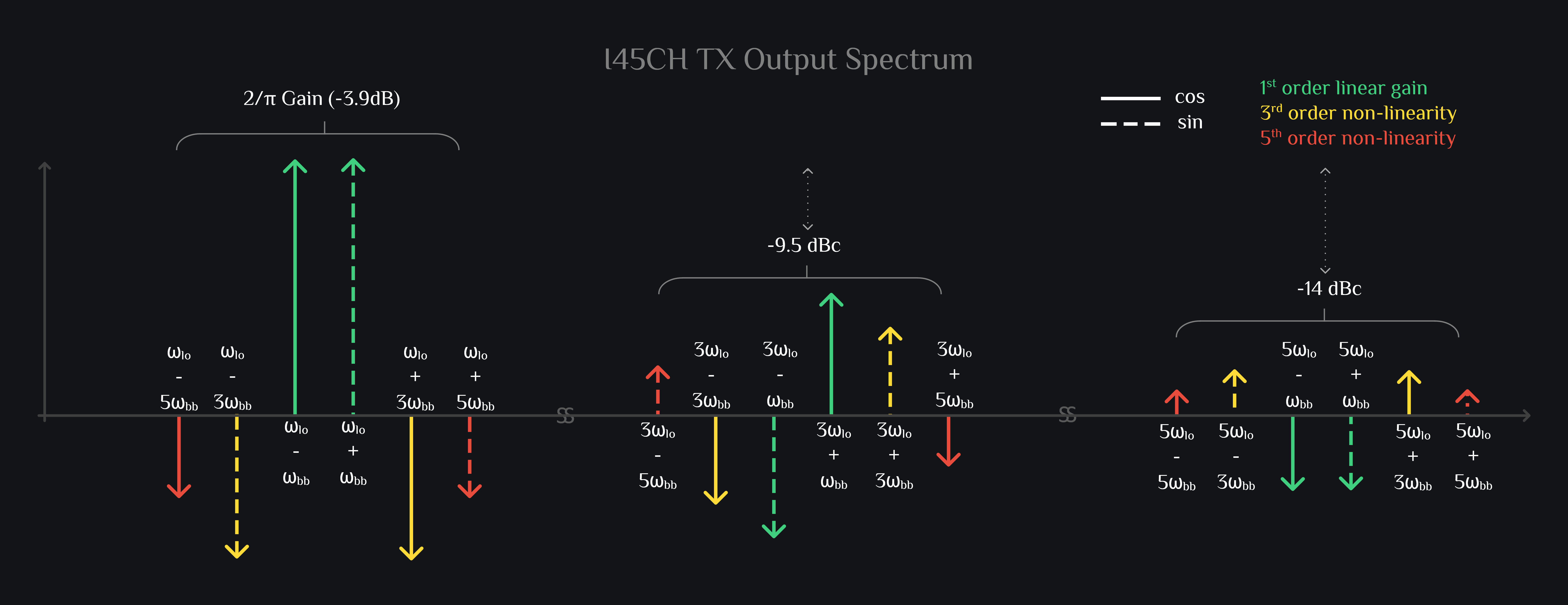
Nothing much here. Similar story as of I channel amplitude-wise. Just phases of the intermodulation products are different (and that is what we want, let them be, we are counting on it, we want distortions to go out of phase such that we we combine different channels, we knock them out)

Q Channel Mixer Output

\[ \left[ \textcolor{#40ce80}{A_1\,\textcolor{#40ce80}{sin(\omega_{bb}\,t)}}-\textcolor{#feda39}{A_3\,\textcolor{#feda39}{sin(3\omega_{bb}\,t)}}+\textcolor{#e74c3c}{A_5\,\textcolor{#e74c3c}{sin(5\omega_{bb}\,t)}} \right]. \left[ \textcolor{#FFFFFF}{\frac{4}{\pi}\textcolor{#FFFFFF}{sin(\omega_{lo}\,t)}+\frac{1}{3}\textcolor{#FFFFFF}{sin(3\omega_{lo}\,t)}+\frac{1}{5}\textcolor{#FFFFFF}{sin(5\omega_{lo}\,t)}}\right]\\ \] \begin{alignat*}{8} \\ =\frac{4}{\pi} \biggr[ & \textcolor{#40ce80}{A_1sin(\omega_{bb}\,t)}.\textcolor{#FFFFFF}{sin(\omega_{lo}\,t)}\;&+&\;\frac{\textcolor{#40ce80}{A_1}}{\textcolor{#FFFFFF}{3}}\textcolor{#40ce80}{sin(\omega_{bb}\,t)}.\textcolor{#FFFFFF}{sin(3\omega_{lo}\,t)}\;&+&\;\frac{\textcolor{#40ce80}{A_1}}{\textcolor{#FFFFFF}{5}}\textcolor{#40ce80}{sin(\omega_{bb}\,t)}.\textcolor{#FFFFFF}{sin(5\omega_{lo}\,t)}\\ -& \textcolor{#feda39}{A_3sin(3\omega_{bb}\,t)}.\textcolor{#FFFFFF}{sin(\omega_{lo}\,t)}\;&-&\;\frac{\textcolor{#feda39}{A_3}}{\textcolor{#FFFFFF}{3}}\textcolor{#feda39}{sin(3\omega_{bb}\,t)}.\textcolor{#FFFFFF}{sin(3\omega_{lo}\,t)}\;&-&\;\frac{\textcolor{#feda39}{A_3}}{\textcolor{#FFFFFF}{5}}\textcolor{#feda39}{sin(3\omega_{bb}\,t)}.\textcolor{#FFFFFF}{sin(5\omega_{lo}\,t)}\\ +& \textcolor{#e74c3c}{A_5sin(5\omega_{bb}\,t)}.\textcolor{#FFFFFF}{sin(\omega_{lo}\,t)}\;&+&\;\frac{\textcolor{#e74c3c}{A_5}}{\textcolor{#FFFFFF}{3}}\textcolor{#e74c3c}{sin(5\omega_{bb}\,t)}.\textcolor{#FFFFFF}{sin(3\omega_{lo}\,t)}\;&+&\;\frac{\textcolor{#e74c3c}{A_5}}{\textcolor{#FFFFFF}{5}}\textcolor{#e74c3c}{sin(5\omega_{bb}\,t)}.\textcolor{#FFFFFF}{sin(5\omega_{lo}\,t)} \biggr] \\ \\ =\frac{2}{\pi} \biggr[ & \textcolor{#40ce80}{A_1\{cos(\omega_{lo}-\omega_{bb})t-cos(\omega_{lo}+\omega_{bb})t\}}\;&+&\;\textcolor{#40ce80}{\frac{A_1}{3}\{cos(3\omega_{lo}-\omega_{bb})t-cos(3\omega_{lo}+\omega_{bb})t\}}\;&+&\;\textcolor{#40ce80}{\frac{A_1}{5}\{cos(5\omega_{lo}-\omega_{bb})t-cos(5\omega_{lo}+\omega_{bb})t\}}\\ -& \textcolor{#feda39}{A_3\{cos(\omega_{lo}-3\omega_{bb})t-cos(\omega_{lo}+3\omega_{bb})t\}}\;&-&\;\textcolor{#feda39}{\frac{A_3}{3}\{cos(3\omega_{lo}-3\omega_{bb})t-cos(3\omega_{lo}+3\omega_{bb})t\}}\;&-&\;\textcolor{#feda39}{\frac{A_3}{5}\{cos(5\omega_{lo}-3\omega_{bb})t-cos(5\omega_{lo}+3\omega_{bb})t\}}\\ +& \textcolor{#e74c3c}{A_5\{cos(\omega_{lo}-5\omega_{bb})t-cos(\omega_{lo}+5\omega_{bb})t\}}\;&+&\;\textcolor{#e74c3c}{\frac{A_5}{3}\{cos(3\omega_{lo}-5\omega_{bb})t-cos(3\omega_{lo}+5\omega_{bb})t\}}\;&+&\;\textcolor{#e74c3c}{\frac{A_5}{5}\{cos(5\omega_{lo}-5\omega_{bb})t-cos(5\omega_{lo}+5\omega_{bb})t\}}\biggr]\\ \end{alignat*}
TX IQ Mixer, TX HRM Mixer, Q channel

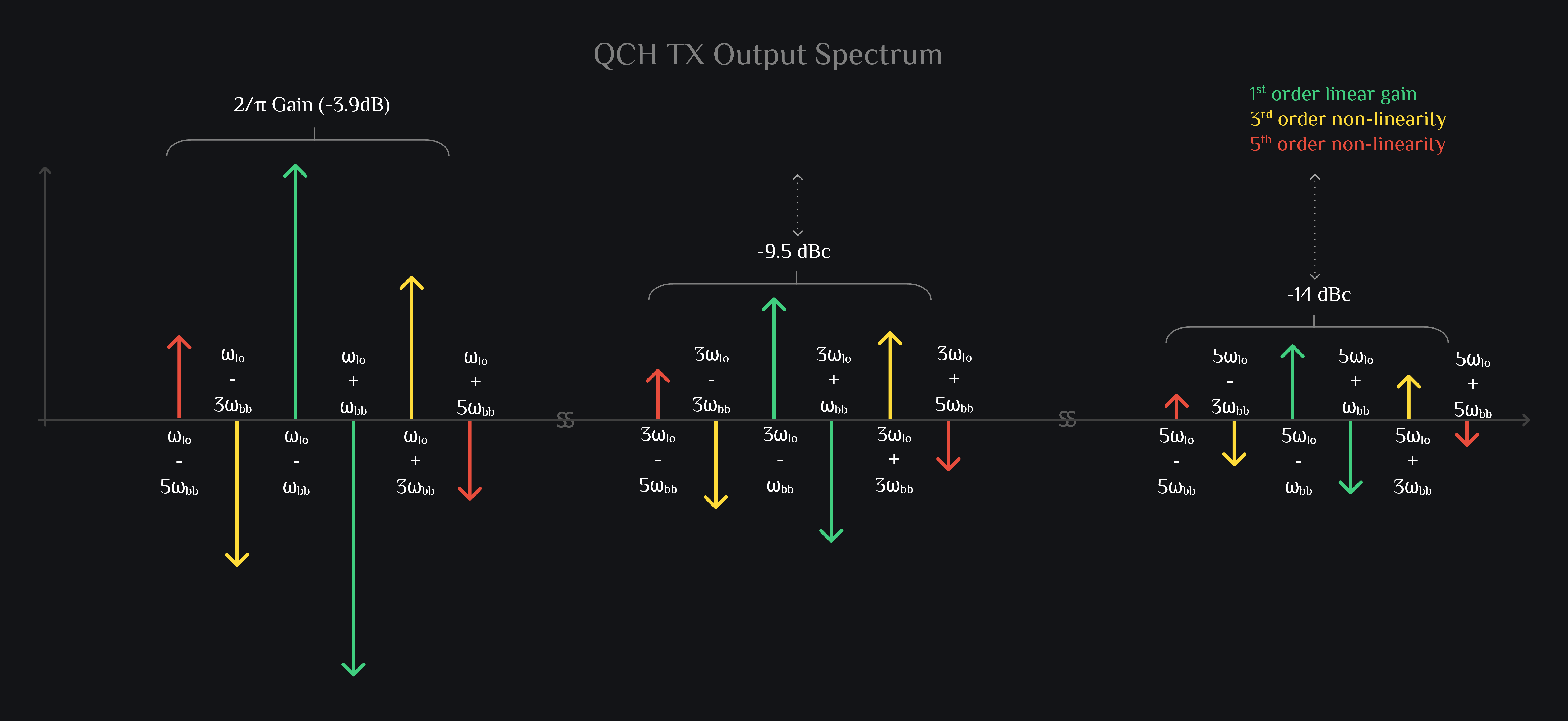
Again nothing much. A typical double side band spectrum. But you can already start noticing here that \(\omega_{bb}\)+\(\omega_{lo}\) has gone out of phase, which means when we combine I and Q channel, it will cancel and we will achieve what is referred as single side band modulation.

Q45 Channel Mixer Output

\[ \left[ \textcolor{#40ce80}{A_1\,\textcolor{#40ce80}{sin(\omega_{bb}\,t)}}-\textcolor{#feda39}{A_3\,\textcolor{#feda39}{sin(3\omega_{bb}\,t)}}+\textcolor{#e74c3c}{A_5\,\textcolor{#e74c3c}{sin(5\omega_{bb}\,t)}} \right]. \left[ \textcolor{#FFFFFF}{\frac{4}{\pi}\textcolor{#FFFFFF}{sin(\omega_{lo}\,t)}+\frac{1}{3}\textcolor{#FFFFFF}{sin(3\omega_{lo}\,t)}+\frac{1}{5}\textcolor{#FFFFFF}{sin(5\omega_{lo}\,t)}}\right]\\ \] \begin{alignat*}{8} \\ =\frac{4}{\pi} \biggr[ & \textcolor{#40ce80}{A_1sin(\omega_{bb}\,t)}.\textcolor{#FFFFFF}{sin(\omega_{lo}\,t)}\;&+&\;\frac{\textcolor{#40ce80}{A_1}}{\textcolor{#FFFFFF}{3}}\textcolor{#40ce80}{sin(\omega_{bb}\,t)}.\textcolor{#FFFFFF}{sin(3\omega_{lo}\,t)}\;&+&\;\frac{\textcolor{#40ce80}{A_1}}{\textcolor{#FFFFFF}{5}}\textcolor{#40ce80}{sin(\omega_{bb}\,t)}.\textcolor{#FFFFFF}{sin(5\omega_{lo}\,t)}\\ -& \textcolor{#feda39}{A_3sin(3\omega_{bb}\,t)}.\textcolor{#FFFFFF}{sin(\omega_{lo}\,t)}\;&-&\;\frac{\textcolor{#feda39}{A_3}}{\textcolor{#FFFFFF}{3}}\textcolor{#feda39}{sin(3\omega_{bb}\,t)}.\textcolor{#FFFFFF}{sin(3\omega_{lo}\,t)}\;&-&\;\frac{\textcolor{#feda39}{A_3}}{\textcolor{#FFFFFF}{5}}\textcolor{#feda39}{sin(3\omega_{bb}\,t)}.\textcolor{#FFFFFF}{sin(5\omega_{lo}\,t)}\\ +& \textcolor{#e74c3c}{A_5sin(5\omega_{bb}\,t)}.\textcolor{#FFFFFF}{sin(\omega_{lo}\,t)}\;&+&\;\frac{\textcolor{#e74c3c}{A_5}}{\textcolor{#FFFFFF}{3}}\textcolor{#e74c3c}{sin(5\omega_{bb}\,t)}.\textcolor{#FFFFFF}{sin(3\omega_{lo}\,t)}\;&+&\;\frac{\textcolor{#e74c3c}{A_5}}{\textcolor{#FFFFFF}{5}}\textcolor{#e74c3c}{sin(5\omega_{bb}\,t)}.\textcolor{#FFFFFF}{sin(5\omega_{lo}\,t)} \biggr] \\ \\ =\frac{2}{\pi} \biggr[ & \textcolor{#40ce80}{A_1\{cos(\omega_{lo}-\omega_{bb})t-sin(\omega_{lo}+\omega_{bb})t\}}\;&+&\;\textcolor{#40ce80}{\frac{A_1}{3}\{sin(3\omega_{lo}-\omega_{bb})t+cos(3\omega_{lo}+\omega_{bb})t\}}\;&+&\;\textcolor{#40ce80}{\frac{A_1}{5}\{-cos(5\omega_{lo}-\omega_{bb})t+sin(5\omega_{lo}+\omega_{bb})t\}}\\ -& \textcolor{#feda39}{A_3\{-sin(\omega_{lo}-3\omega_{bb})t+cos(\omega_{lo}+3\omega_{bb})t\}}\;&-&\;\textcolor{#feda39}{\frac{A_3}{3}\{cos(3\omega_{lo}-3\omega_{bb})t+sin(3\omega_{lo}+3\omega_{bb})t\}}\;&-&\;\textcolor{#feda39}{\frac{A_3}{5}\{sin(5\omega_{lo}-3\omega_{bb})t-cos(5\omega_{lo}+3\omega_{bb})t\}}\\ +& \textcolor{#e74c3c}{A_5\{-cos(\omega_{lo}-5\omega_{bb})t+sin(\omega_{lo}+5\omega_{bb})t\}}\;&+&\;\textcolor{#e74c3c}{\frac{A_5}{3}\{-sin(3\omega_{lo}-5\omega_{bb})t-cos(3\omega_{lo}+5\omega_{bb})t\}}\;&+&\;\textcolor{#e74c3c}{\frac{A_5}{5}\{cos(5\omega_{lo}-5\omega_{bb})t-sin(5\omega_{lo}+5\omega_{bb})t\}}\biggr]\\ \end{alignat*}
TX IQ Mixer, TX HRM Mixer, Q45 channel

Great, \(\omega_{bb}\)+\(\omega_{lo}\) is out of phase of I45 CH. Things are moving in right direction.

I & Q Mixer Output Combined

Now this is where it gets interesting. When I and Q channel outputs are added, a lot of products cancel out. These tones are left out:

\begin{alignat*}{8} \frac{4}{\pi} \biggr[ & \textcolor{#40ce80}{A_1cos(\omega_{lo}-\omega_{bb})t}\;&-&\;\textcolor{#40ce80}{\frac{A_1}{3}cos(3\omega_{lo}+\omega_{bb})t}\;&+&\;\textcolor{#40ce80}{\frac{A_1}{5}cos(5\omega_{lo}-5\omega_{bb})t}\\ +& \textcolor{#feda39}{A_3cos(\omega_{lo}+3\omega_{bb})t}\;&-&\;\textcolor{#feda39}{\frac{A_3}{3}cos(3\omega_{lo}-3\omega_{bb})t}\;&+&\;\textcolor{#feda39}{\frac{A_3}{5}(5\omega_{lo}+3\omega_{bb})t}\\ +& \textcolor{#e74c3c}{A_5cos(\omega_{lo}-5\omega_{bb})t}\;&-&\;\textcolor{#e74c3c}{\frac{A_5}{3}cos(3\omega_{lo}+5\omega_{bb})t}\;&+&\;\textcolor{#e74c3c}{\frac{A_5}{5}cos(5\omega_{lo}-5\omega_{bb})t}\biggr]\\ \end{alignat*}
TX IQ Mixer Spectrum

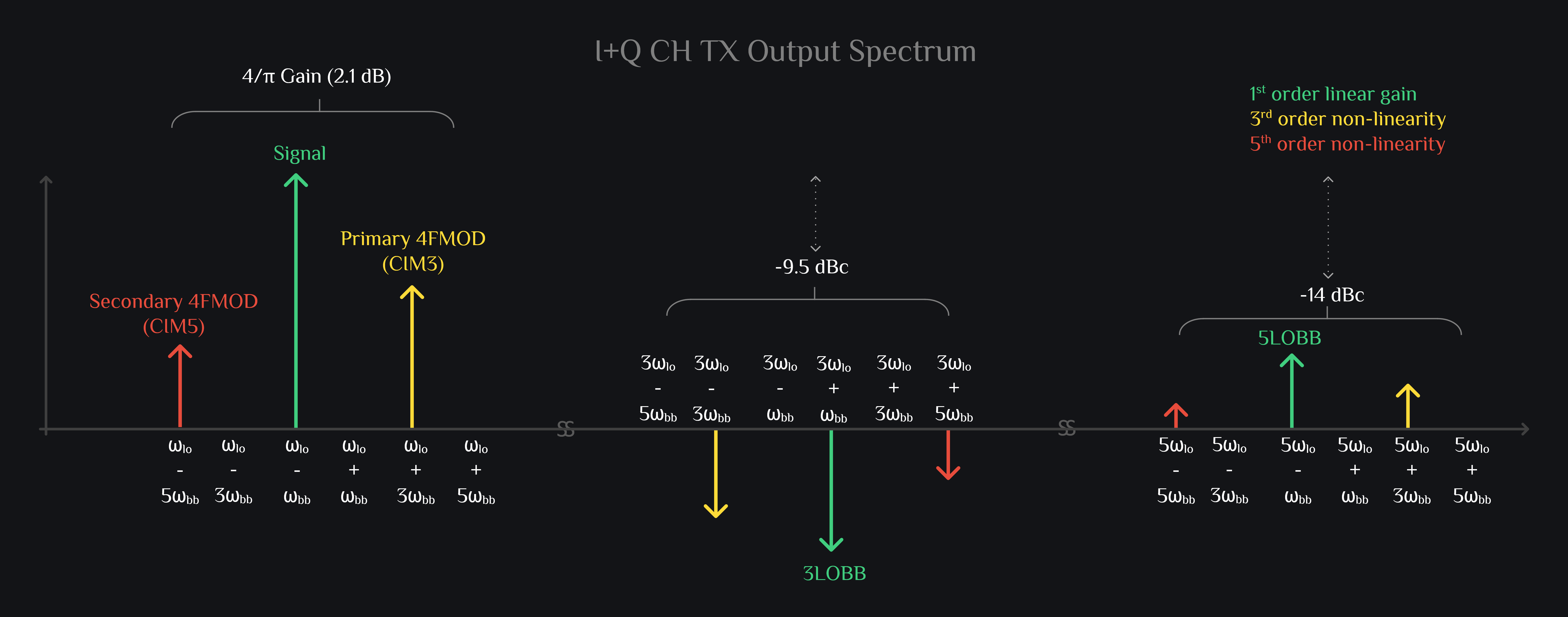
This is what you can expect to see in most of the transmitters. Not every TX is HRM, but almost all are IQ. So in IQ TX, you get your desired signal, \(\omega_{lo}\)-\(\omega_{bb}\), with \(\frac{4}{\pi}\) gain, and two distortion products which fall very close: The 4FMODs. Also if you are wondering why \(\omega_{lo}\)-\(\omega_{bb}\), why didn’t we get \(\omega_{lo}\)+\(\omega_{bb}\)? This is because we assigned phases such that I led Q, if you make Q lead I, you get \(\omega_{lo}\)+\(\omega_{bb}\).

I45 & Q45 Output Combined

TX IQ Mixer, TX HRM Mixer, I45+Q45 channel

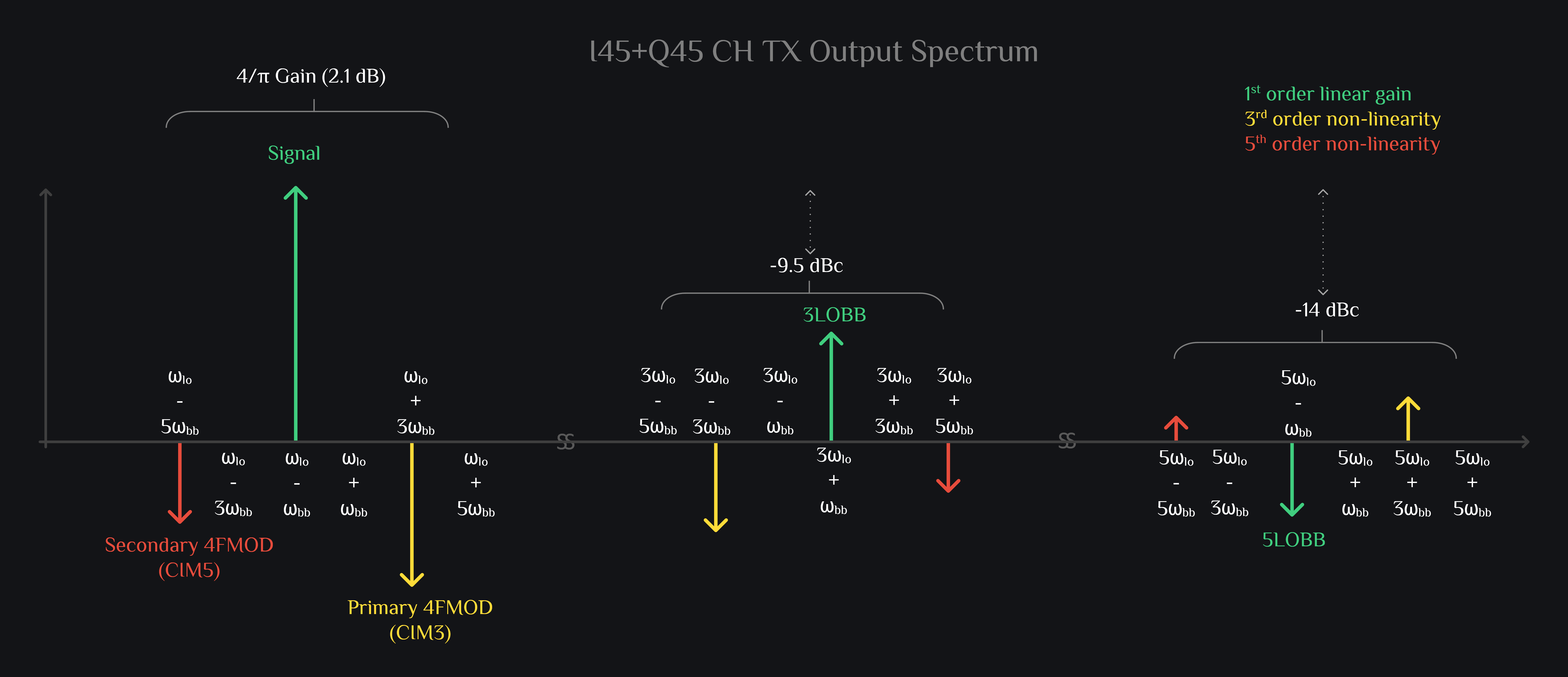
Just another SSB TX but observe the phases. Did we get it right? Are we in a position to cancel junk like 4FMODs, 3LOBB etc.

All Channels Combined

If you answered yes to above question, we wouldn’t be surprised. Thanks for sticking around. Yes, when you combine IQ mixer with I45Q45 mixer, you end up canceling a lot of trash while your signal adds in phase (nitpicking: they are 45deg out of phase, don’t be so harsh, let us still call them in phase). Did we hear win-win? Yea maybe except that now are probably burning twice the DC power as of IQ mixer, and cancellation is always sensitive to mismatches. If all the stars don’t align and things don’t behave over process and temperature, you get limited cancellation. Yea you might have solved it in math, but you are not done. But hey, this is a great start! At least you are starting with strong fundamentals. You have the necessary mathematical background and insights before you delve into design or debug existing design for that matter.

TX HRM Mixer Spectrum

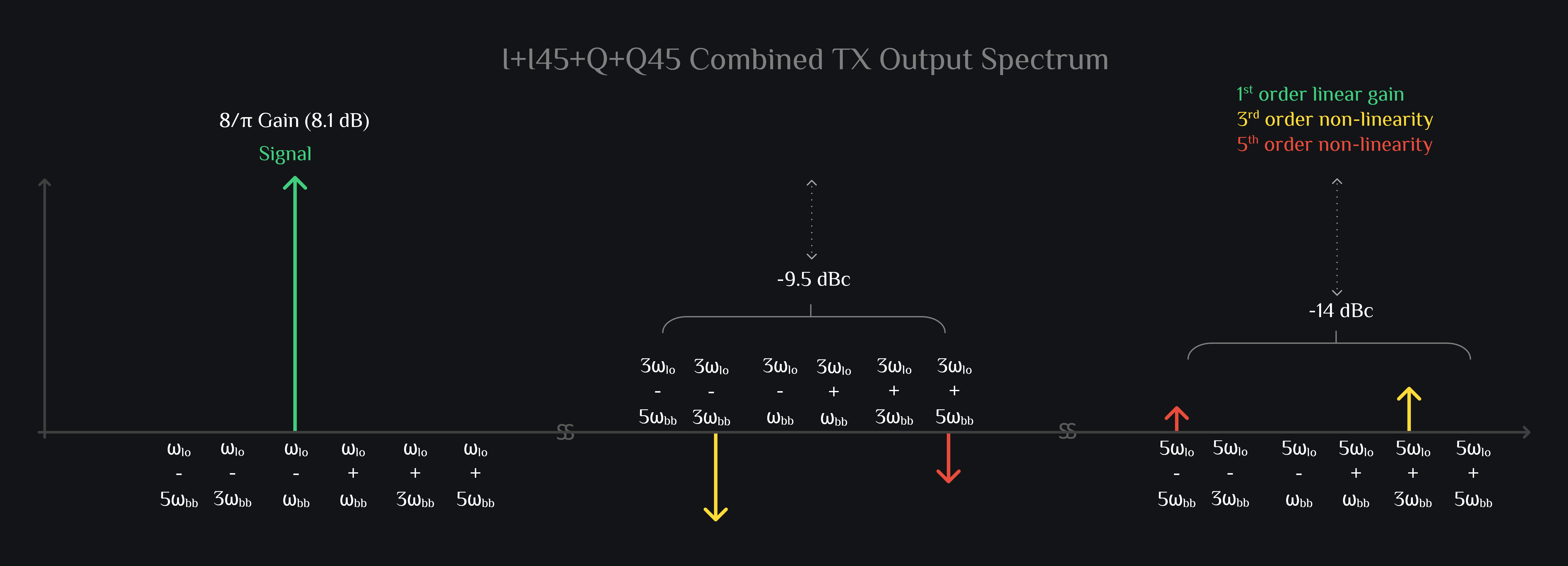
At output of HRM mixer, you have your desired signal, \(\omega_{lo}\)-\(\omega_{bb}\), with \(\frac{8}{\pi}\) gain, and some intermods are still left. Sad but ok these are low enough in magnitude that hopefully they wouldn’t bite you. Just to get an idea, see now how close our HRM output signal looks like to ideal signal (even though we shot ourselves in foot by assuming big non-linearity \(A_{3}=0.1\) and \(A_{5}=0.05\)), plot below compares the two.

RFInsights

Published: 22 Dec 2022
Last Edit: 08 Jun 2023